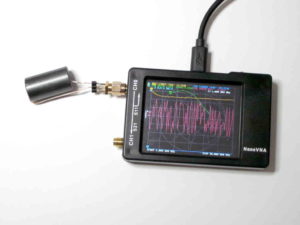
W0SJ matching transformer for an EFLW (Laird 28B1540-000)

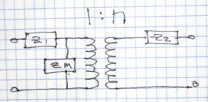
QST publishes a design by W0SJ for a nominal 50:450Ω EFLW matching device from 160-10m using the following circuit.

The article is ‘in-brief’ as technical stuff that will not interest most hams is published privately on a members-only page. This article is based on the information in the QST article alone (ie not on the private members only supplementary information).

The core has a modest price in North America, but shipping to other parts of the world may make it very expensive… IOW unobtainium to most parts of the world.

Above is the published InsertionLoss. The article states that they were half the value obtained in a back to back measurement, and it should be noted that is a compromised measurement, and secondly that InsertionLoss comprises two components, (dissipative) Loss and MismatchLoss. Continue reading W0SJ matching transformer for an EFLW (Laird 28B1540-000)

Online expert on coax loss

An online expert opined:

Whether your antenna is a perfect 1:1 or a 10:1, a 50 foot length of coax will have HALF the loss of the exact same coax on the exact same antenna system as measured with the 100 foot piece.

Is it true? Can we learn from it?

Let’s take a worked example of Belden 8259 (RG58A/U) with a load of 5+j0Ω at 146MHz. VSWR is approximately 10. Continue reading Online expert on coax loss

Voltage symmetry of practical Ruthroff 1:1 baluns

Well, I guess Voltage symmetry of practical Ruthroff 4:1 baluns begs the question, what about Ruthroff 1:1 voltage baluns?

The Ruthroff 1:1 voltage balun can be seen as two back to back Ruthroff 4:1 voltage baluns with the redundant winding removed… and that prompts the thinking that the cascade of two baluns back to front might cancel the phase delay.

Let’s measure a popular Ruthroff 1:1 voltage balun.

RAK BL-50A

Above, the RAK BL-50A was a quite popular balun, and probably the balun of choice for half wave dipoles… well until the message about current baluns escaped. Continue reading Voltage symmetry of practical Ruthroff 1:1 baluns

Voltage symmetry of practical Ruthroff 4:1 baluns

Much is written about antenna system balance, this article looks at balance issues with the very common ATU configuration that uses a Ruthroff 4:1 voltage balun to adapt coax transmitter output to two wire open feed line. This type of balun is employed in most ham market ATUs that contain an integral balun.

Above is Ruthroff’s equivalent circuit, Fig 3 from his paper (Ruthroff 1959).

If one looks carefully at the transmission line form, there is effectively a two wire line wound into a helix (usually on a magnetic core) and connected from the unbalanced source to one half of the load inverting the connection for the necessary phase reversal.

Ideally, Vout of this line is equal to Vin, ie Vout/Vin should be 1∠0°. That is unlikely as it implies a zero length transmission line which provides the decoupling of the phase inverting line.

This article looks at the Ruthroff 4:1 balun balance using the very popular MFJ-949E as an example.

Above is a pic of the MFJ-949E Ruthroff 4:1 balun. The transmission line is not uniform, but let’s make an approximation to predict its behavior with a centre tapped 100Ω load, the centre of which is connected to the ground terminal. Continue reading Voltage symmetry of practical Ruthroff 4:1 baluns

Equivalent circuit of an antenna system

Common practice is to treat antenna systems as a two terminal device in free space.

Pickup most handbooks, and even text books, and antennas and often antenna systems are described in this way.

That model is quite inadequate for many or most antenna systems installed in proximity of natural ground. For example, a two terminal dipole and feed line system representation cannot have feed line common mode current, and it follows that thinking in terms of two terminal models denies a full understanding of the antenna system.

A three terminal model of an antenna system

(Schmidt nd) sets out a three terminal model of an antenna system in presence of ground using quite conventional linear circuit theory.

Above is Schmidt’s Y network based on values of three intermediate impedances, ZD, ZU, and ZC. These are found from measured values Za, Zb and ZC as explained by Schmidt: Continue reading Equivalent circuit of an antenna system

AIM 916 produces internally inconsistent results


AIMuhf

AIM915a was recently pulled from the distribution site and replaced by a new release, AIM916.

AIM916 chokes on some calibration files created with earlier versions, so again historical scan data is rendered worthless. Note the illogical diagnostic message… typical AIM quality.

I cannot recall ever finding a new release that did not have significant defects, commonly inconsistency between displayed values. In the common theme of one step forward, two steps backwards, this version has defects that were not present in AIM910B.

This problem existed in AIM915a, it persists in AIM916.

Let’s review the internal consistency of this part of the display screen.

Most of the values given above are calculated from a single measurement value, and should be internally consistent. That measurement value is translated to different quantities, many based on the stated Zref (50Ω in this case). Continue reading AIM 916 produces internally inconsistent results

VU3SQM directional wattmeter build – #4

VU3SQM directional wattmeter build – #1 laid out the first steps in design review and build of a directional wattmeter.

At long last, some PTFE rod arrived to permit assembly of the transformers.

For reasons discussed in an earlier article, the transformers use a larger core than the original VU3SQM. They need to stand above the board, and whilst that compromises the mechanical strength of the assembly, it should have better performance. Continue reading VU3SQM directional wattmeter build – #4

W5KV’s transmitting loop measurements – DELUXE HG-1 PreciseLOOP 7MHz

W5KV documented his measurements of a 3m perimeter circular transmitting loop, DELUXE HG-1 PreciseLOOP, 2.0m centre height above ground.

This article explores his 7MHz observations.

Assuming the measurements were made with the antenna clear of disturbing conductors etc, in good condition.

Above is his VSWR scan.

The key measurements were:

  • centre frequency 7.175MHz, VSWRmin=1.1;
  • VSWR=3 bandwidth 36kHz.

Based on that, we can estimate the half power bandwidth to be 30kHz if R is less than Ro, more like 33kHz in the other case, but we will be optimists.

A NEC-4.2 model of the antenna at 14MHz was built and calibrated to the implied half power bandwidth (30kHz). Model assumptions include:

  • ‘average’ ground (σ=0.005, εr=13);
  • Q of the tuning capacitor = 2000;
  • conductivity of the loop conductor adjusted to calibrate the model half power bandwidth to measurement.

Note that the model may depart from the actual test scenario in other ways.

Above is the VSWR scan of the calibrated model, the load is matched at centre frequency and half power bandwidth is taken as the range between ReturnLoss=6.99dB points. Continue reading W5KV’s transmitting loop measurements – DELUXE HG-1 PreciseLOOP 7MHz

Measuring common mode current with a scope

I wrote recently of a flawed test of balance performance of an antenna system and an ATU, and some readers have taken up the issue, basically asking the question “then, how do you measure balance of a two wire line with a scope?”

The first step is that you must define what you mean by “balance”.

For most wire HF antennas, the balance objective should be equal but opposite currents in the adjacent wires at all locations along the line (recalling the currents may vary along the line). This reduces radiation from the feed line (which can cause EMC problems with nearby appliances / systems), and reduces very local noise pickup on receive (from those same appliances / systems).

Let’s take KA0KA’s scope display from the reference article, but assume that they were taken from current probes so that we are directly measuring feed line currents rather than voltage. Current probes allow the scope to measure current on a conductor placed through the probe, an RF current probe (or current transformer) can be as simple as a suitable ferrite toroid with the primary conductor passing once through the center of the core, and a secondary winding of 10-30 turns loaded with a low value resistor, and the scope input connected across the resistor.

The obvious measurement method

Above, the first measurement shows both channels, and the currents appear almost equal in magnitude and almost opposite in phase, but it does appear that there is a slight phase difference, perhaps 5-15° from exactly opposite phase. Each channel is almost 2div peak to peak, and let’s assume the calibration factor is 1A/div. Continue reading Measuring common mode current with a scope

Australian amateur population trends 1998 – 2018

This is a 2018 update of an article written originally in October 2005, earlier editions published on VK1OD.net which is now offline.

Over recent years to 2002, the number of issued amateur licences was declining, the trend was about 2.8% pa decline over the five years to 2002.

This has concerned some people, who took the view that the decline was a harbinger of the impending demise of Amateur Radio. Continue reading Australian amateur population trends 1998 – 2018