Cooling an IC2200H – update #2

I have described a solution an overheating problem with my IC2200H at Cooling an IC2200H.

IC2000HCoolingAnother solution for control of the fan to minimise nuisance draft and noise is one of the inexpensive digital thermostats on eBay.

I reviewed one of these things at Review of inexpensive Chinese thermostat – MH-1210. It had its issues, but as modified for 12VDC operation, I tested it for control of the fan in the above pic.

cctstat01Above is the thermostat, though modified, purchased for about A$12 including post and the sensor thermistor. Don’t buy the MH-1210 as some at least are shipped with incorrect calibration. Continue reading Cooling an IC2200H – update #2

VK3IL’s 3m circumference LDF4-50B loop on 20m

David, VK3IL, describes a small transmitting loop (STL) at Portable magnetic loop antenna.

At VK3IL’s 3m circumference LDF4-50B loop on 40m. I reviewed his loop behaviour on 40m, and its efficiency was quite low… though typical of a loop of that size at that frequency.

Radiation resistance of a STL is proportional to the fourth power of frequency, and since it is often dwarfed by loss resistance, we should expect that doubling frequency will dramatically improve performance.

As far as I can glean from the article, it is made from a 3m length of LDF4-50B Heliax, and uses a Patterson match to tune it.

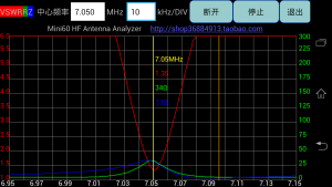
Clip 153David offered measurement of VSWR around centre frequency for the loop approximately matched (VSWR=1.24) on 20m. He has measured the VSWR=2.86 bandwidth shown between markers 2 and 3 to be 45kHz. Continue reading VK3IL’s 3m circumference LDF4-50B loop on 20m

Enhancement of Calculate small transmitting loop gain from bandwidth measurement

At Efficiency and gain of Small Transmitting Loops (STL) I explained an approach to assessing the gain the efficiency of STL, and provided a link to a calculator to perform the calcs.

This expands on application of the concepts and introduces an enhanced calculator to perform the calculations.

Clip 222

Firstly, this technique applies to antennas where the VSWR characteristic is consistent with a feed point or virtual feed point where around the frequency of minimum VSWR, X varies with frequency much more than R. The simplified analysis assumes that R is constant, and change in X is the reason for the VSWR characteristic. See VSWR curve of a simple series resonant antenna for more information. Continue reading Enhancement of Calculate small transmitting loop gain from bandwidth measurement

VK3IL’s 3m circumference LDF4-50B loop on 40m

David, VK3IL, describes a small transmitting loop (STL) at Portable magnetic loop antenna.

As far as I can glean from the article, it is made from a 3m length of LDF4-50B Heliax, and uses a Patterson match to tune it.

Clip 150David offered measurement of VSWR around centre frequency for the loop matched on 40m. He has measured the VSWR=2.6 (the half power) bandwidth shown between markers 2 and 3 to be 22kHz. Continue reading VK3IL’s 3m circumference LDF4-50B loop on 40m

Cooling an IC2200H – update

IC2000HCooling2

I have an IC2200H mounted on my operating table with 25mm clearance above the radio and ample room for convection currents to assist in heat removal. It is concerning that the case temperature reaches temperatures that are not safe to touch, temperatures in excess of 75° (55° above ambient) have been measured and that has not triggered the internal temperature protection… so it could get hotter still!

Whilst it might take a while for the radio to reach high temperatures, in the long term, it must dissipate around 139W when transmitting on HIGH power setting and at ambient temperatures as high as 35° in the shack. (Rated input is 15A at 13.6V for 65W out, leaving 139W of heat to be dissipated.)

This is one of those high power mobile radios that advertises no fan as an advantage, but it is clearly not up to the task!

The objective of this change is to keep the external parts below 60°, the (ASTM standard C1055  1999) 5 second human skin burn threshold.

Continue reading Cooling an IC2200H – update

VK3YE’s 3m circumference copper tube loop with RG213 stub tuning

Peter, VK3YE, describes a small transmitting loop (STL) in his video at https://www.youtube.com/watch?v=Cv_RnLpZ9gw.

? 100 watt 7 MHz magnetic loop for units and apartments - YouTube - Mozilla Firefox firefox 04/08/2015 , 07:24:25

As far as I can glean from the video, it is made from a 3m length of copper tube 19mm diameter, and uses about 1.8m of RG213 to tune it, and appears to have its centre 0.7m above ‘ground’ .

Let us firstly look at a free space model of the antenna using Reg Edwards’ RJELoop1 tool.

Screenshot - 07_06_2015 , 09_53_12

This model has its limitations, but the calculated inductance is of interest. We can calculate the inductive reactance to be 118Ω. The capacitive stub of RG213 will need around 107Ω reactance, and solving for RG213, we find that 1.94m gives 0.19-j107Ω. The resistive component is important as it is ignored by the above model. The stub resistance is a loss resistance, and we need to recalculate the efficiency. Efficiency=Rrad/Rloss=0.005/(0.19+0.0351+0.005)=2.17% (-16.6dB). We can also calculate the Q as 107/(0.19+0.0351+0.005)=465 and half power bandwidth as 7100/497=15.3kHz. Continue reading VK3YE’s 3m circumference copper tube loop with RG213 stub tuning

2.4:1 balun design failure

A lost soul searching for enlightenment on impedance transformation sought advice on a transformer at 2.4 : 1 BALUN.

Inevitably one of the forum experts counselled:

Assuming your quad is a single-band HF antenna, a conventional transformer using #2 powdered iron would be my choice for the balun function. The reactance of the secondary winding would need to be at least 600 ohms.

So, let’s put the forum expert’s advice to a practical test.

Fleshing out the proposed solution

I have at hand a T200-2 core, so lets calculate the secondary turns to satisfy the proposed solution.

Screenshot - 27_05_2015 , 07_05_11

Above is calculation from a popular online calculator. For 14MHz, the secondary should be at least 23.8t. We will use 24t. Continue reading 2.4:1 balun design failure

Thermal observations on Neosid 28-053-31 ferrite toroid

The Neosid 28-053-31 ferrite toroid is used in my HF Balun Project.

This article reports some thermal measurements and analysis made in relation to the project some years ago, but possibly of interest.

HfBalunAbove is the Neosid 28-053-31 ferrite toroid in an implementation of my HF Balun Project using XLPE wire for the winding. The core is a NiZn ferrite toroid of 63x26x19mm (larger than FT240 size). Continue reading Thermal observations on Neosid 28-053-31 ferrite toroid

Interpreting temperature rise in ferrite cored RF transformers and inductors


FT240-43-11t

We often see statements by hams where they draw inference from observed temperature rise of a ferrite core at RF. Lets consider the following statement.

The FT-240-43 balun MUST be quite efficient as it barely increased in temperature over a 5 minute over at 100W on SSB.

For the purpose of this explanation, lets assume barely increased in temperature means 5° increase in temperature from cold. Under these conditions, we can reasonably assume that almost all of the heat input to the core is consumed in raising the core temperature. Continue reading Interpreting temperature rise in ferrite cored RF transformers and inductors

A walk through of a practical application of AIMuhf/AIM900A #2

I mentioned at A walk through of a practical application of AIMuhf/AIM900 that I wasn’t all together happy with feed point R at resonance, at 40Ω it was perhaps a touch high for a 2m quarter wave ground plane on a largish vehicle roof.

AIMuhfRepeated measurement of the DC resistance from the coax plug sheild to car body yielded unstable resistance ranging from 1 to 10Ω. If stable low DC resistance is not achieved, this feed line won’t work properly for RF. Continue reading A walk through of a practical application of AIMuhf/AIM900A #2