From time to time one sees discussion online about consistency of ‘measured’ VSWR at different power levels (on the same instrument).
A question often asked is:
I tune up at 10W and achieve VSWR=1.5, and when I increase power to 100W, the VSWR increases. Which should I believe?
The first thing to note is that good antenna systems SHOULD be linear, VSWR should be independent of power, it is if the system IS linear.
For the most part they are linear, even though many antenna systems contain elements such as ferrite cored inductors that may exhibit some small level of non-linearity in ‘normal’ operation.
Non-linearity caused by for instance saturation of magnetic materials, loss of permeability where the temperature of ferrite cores reaches Curie point, arcing of capacitors or other insulating materials is NOT normal linear operation of a GOOD antenna system. If high indicated VSWR at high power is caused by any of these effects, it is flagging a problem that requires attention.
That said, a significant non-linear element may be the VSWR meter itself.
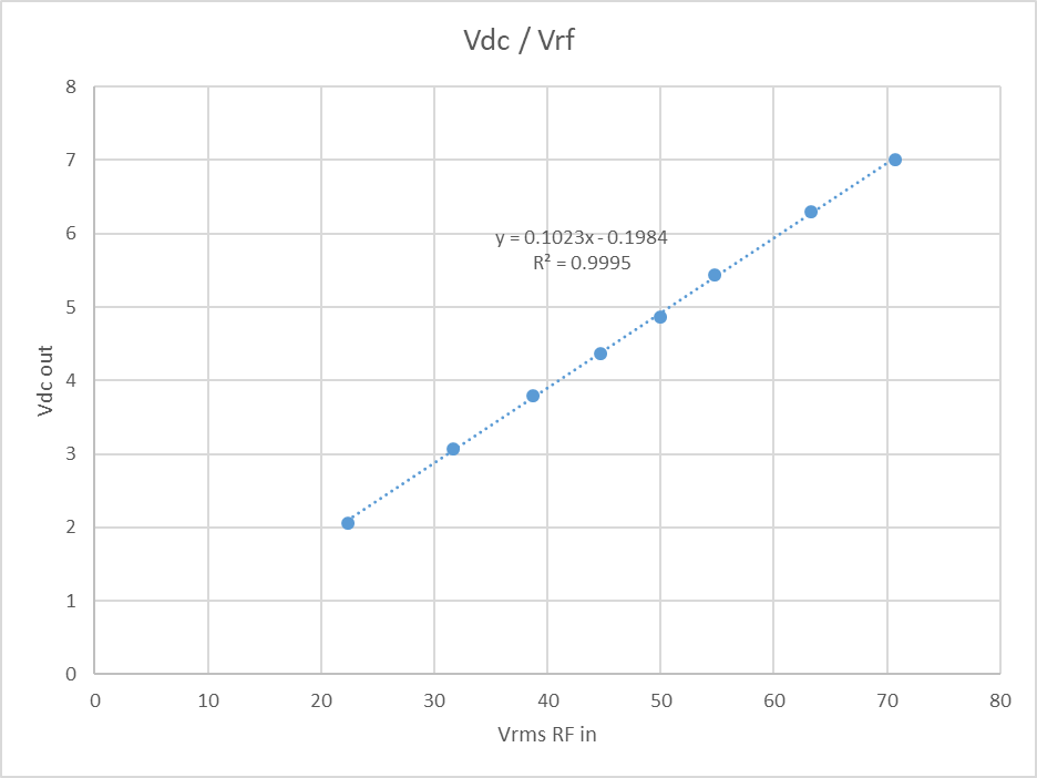
A common, if not most common way to make these meters is to use a half wave detector to convert the direction coupler RF outputs into DC to drive an ordinary moving coil meter. These meters commonly assume that the detector DC output voltage is exactly proportional to the RF input voltage.
Lets look at the accuracy of that process.

Above is a plot of the detector output vs RF input voltage for a commercial 200W VSWR meter. The measurements cover input power from 10 to 100W.
Continue reading VSWR meter trap for the unwary
Last update: 7th August, 2018, 3:47 PM