NanoVNA setup for common antenna system measurement tasks – scripting the setup

NanoVNA setup for common antenna system measurement tasks showed a display configuration better suited to those tasks.

It is tedious to set the display up using the device menu, and setups may vary with different NanoVNA hardware and firmware.

The firmware I used was NanoVNA.H.v1.2.20 which allows some setup using serial port commands. This article describes the technique.

The command used is the trace command

trace {0|1|2|3|all} [logmag|phase|delay|smith|polar|linear|swr|real|imag|r|x|z|zp|g|b|y|rp|xp|sc|sl|pc|pl|q|rser|xser|zser|rsh|xsh|zsh|q21] [src]
trace {0|1|2|3} [lin|log|ri|rx|rlc|gb|glc|rpxp|rplc|rxsh|rxser]
trace {0|1|2|3} {scale|refpos} {value}

For this exercise, I used Teraterm5 which allows setting delays after each character and after each line so that the NanoVNA is not overrun.

Above, the Teraterm serial port setup. Continue reading NanoVNA setup for common antenna system measurement tasks – scripting the setup

NanoVNA setup for common antenna system measurement tasks

A common task is an overall assessment of an antenna system, this article looks at NanoVNA display configuration that will often suit stand alone:

  1. measurement at any point on the feed line; and
  2. measurement with the reference plane, either by direct connection, fixture calibration or approximate calibration using e-delay.

Caution

When measuring an antenna system with the NanoVNA:

  • drain any static charge at the coax connector before offering the connector up to the NanoVNA; and
  • do not leave the instrument attached any longer than necessary to make the measurements.

Case 1: measurement at any point on the feed line

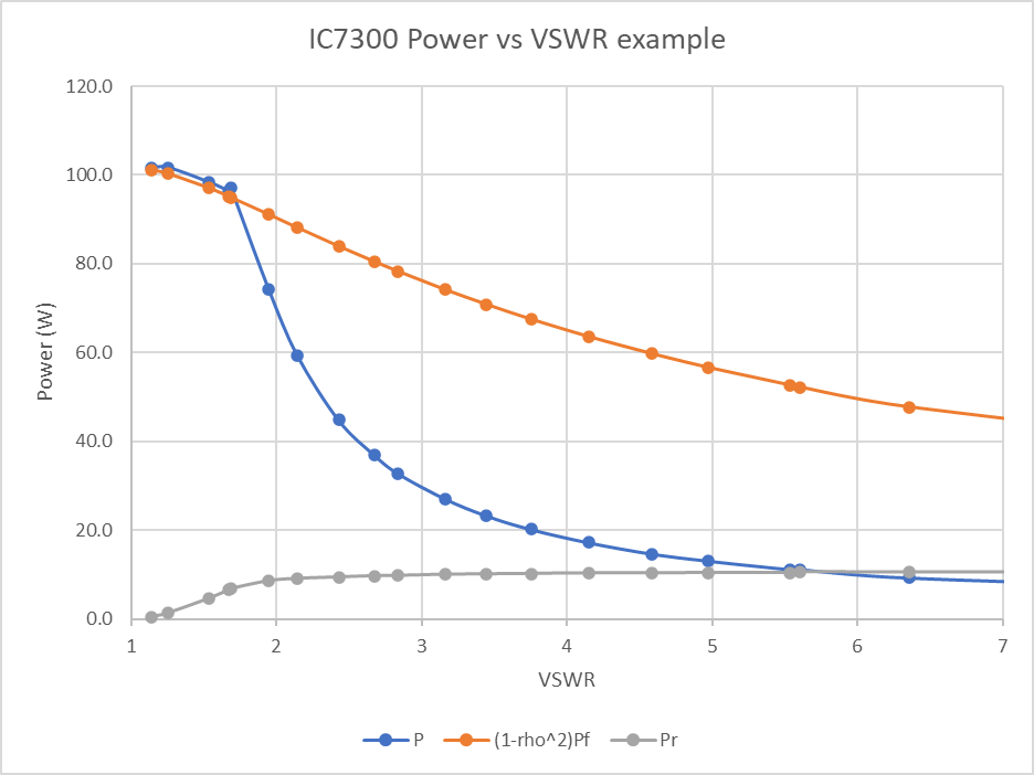
Since the phase relationship of the reflected wave at the point of observation relative to that at the feed point is unknown the only meaningful statistics are those based on the magnitude of s11 (|s11|), |s11|, ReturnLoss, and VSWR.

My NanovVNA does not offer a ReturnLoss plot natively, you could use |s11|dB remembering to multiply all values by -1 (ie ReturnLossdB=-|s11|dB.

Otherwise, the VSWR plot is most useful.

A Smith chart plot of s11 is sort of useful, but there is an unknown rotation from the feed point.

Since they are of no real value, you could disable traces 1, 2 and 3 to make the display less cluttered.

Case 2: measurement with the reference plane at the feed point, either by direct connection, fixture calibration or approximate calibration using e-delay

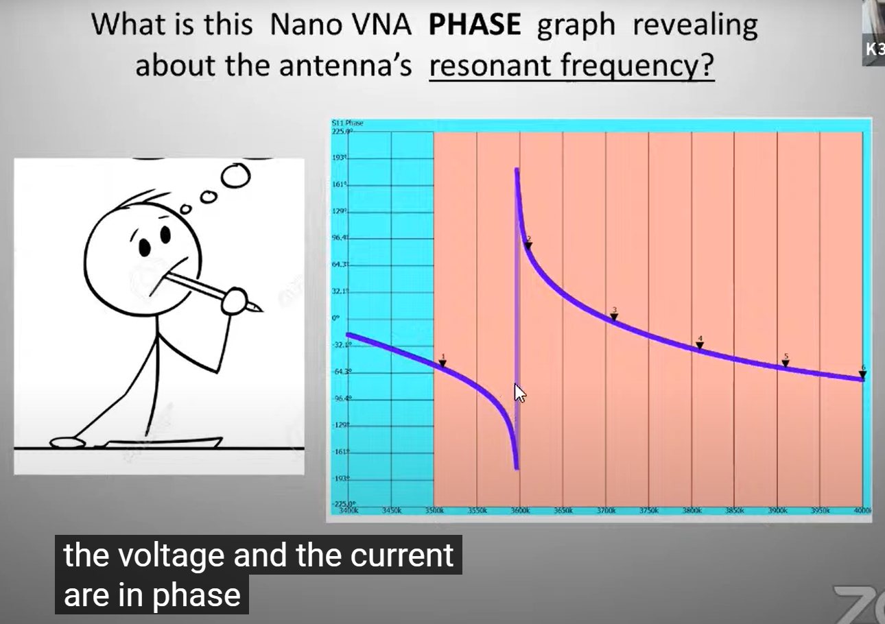
In this case, the phase of s11 is meaningful which means:

  • the Smith chart plot is properly presented wrt the chosen reference plane; and
  • R and X components of impedance can be properly calculated and presented.

An example

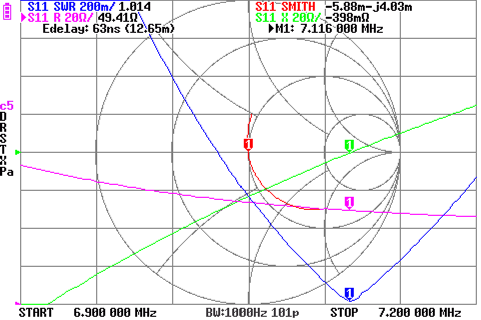
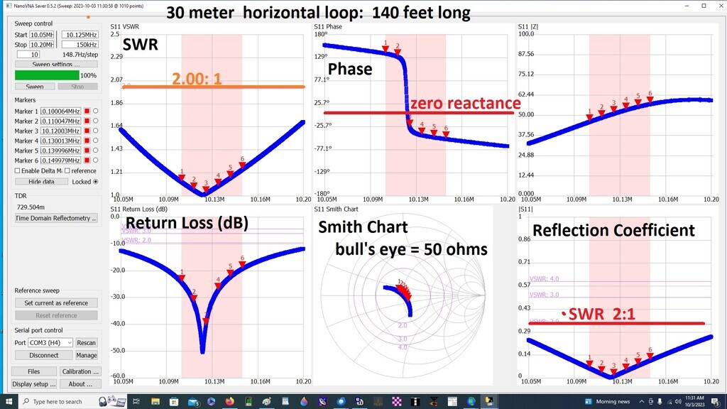
Let’s look at an example antenna sweep where the NanoVNA measurements are wrt the feed point (e-delay has been used as an approximate correction for a short feed line tail). The examples are from NanoVNA.H.v1.2.20 firmware.

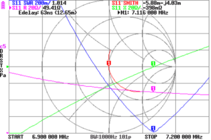
Above is a screen capture, the colours are inverted for printing. Continue reading NanoVNA setup for common antenna system measurement tasks

Fazed by s11 phase magic?

The widespread takeup of the NanoVNA has given new life to the resonance myth. Heard on air some years ago was this enlightenment:

anyone who has blown across the top of an empty milk bottle and observed resonance knows that you really need a resonant antenna to fairly suck the power out of the transmitter.

Phase of s11

Let’s divert to the new pitch that phase of s11 equal to 0° is a key optimisation target.

Adapted to the NanoVNA is this capture from an instructional video:

The voice over is explaining that the (load) voltage and current are in phase at the cursor in this phase of s11 chart (check the axis title). The discussion asserts that phase=0° is goodness. Continue reading Fazed by s11 phase magic?

Voltage baluns are making a comeback for HF antennas – some real antenna measurements

Voltage baluns are making a comeback for HF antennas discussed the application of a common Ruthroff 1:4 (voltage) balun design to a slightly unbalanced theoretical scenario.

This article applies the same analysis to two reported measured dipole cases at 3.6MHz.

G3TXQ dipole system at 3.6MHz

(Hunt 2015) reported measurements of his dipole antenna system at 3.6MHz. Continue reading Voltage baluns are making a comeback for HF antennas – some real antenna measurements

Voltage baluns are making a comeback for HF antennas?

I planned this article to be a Youtube video, but recent behaviors of Google / Youtube give me pause to consider whether or how I use Youtube in the future. So, this article is a simpler presentation of the underlying concepts.

For most purposes, users of HF antennas would like the feed line to perform that function alone, ie to not participate as radiating or pickup conductors.

For that end, we want the common mode component of feed line current to be very very low.

Discussion of antennas tends to represent them as two terminal devices in free space, ie ignoring the presence of ground in close proximity. This applies whether the feed line is coax or two wire line.

A more complete representation (or model) is a three terminal network that includes a terminal to permit current to flow to ground. Above is a Wye or Delta equivalent circuit, and that can be transformed to an equivalent Tee circuit. Continue reading Voltage baluns are making a comeback for HF antennas?

RF compensation of power relays – bigger relays

RF compensation of power relays referred to a video I have recently posted RF compensation of power relays.

Above, the example relay.

So, does this technique work for bigger relays?

Firstly, small is beautiful… it is easier to get good compensation of smaller relays over a wider frequency range.

Above is an example relay by K5UJ for discussion. I do not have measurement data for this relay box, but experience tells me that at HF, the compensation technique discussed above is likely to give good results for its intended purpose as a HF T/R relay. Continue reading RF compensation of power relays – bigger relays

Antenna assessment using NanoVNA – learning from a user example

A recent online posting provides content for learning. K3EUI posted a NanoVNA-Saver screenshot of his antenna described as:

Set out a horizontal loop wire antenna for possible NVIS paths
Wire is about 140 ft length with an outside CLC tuner, fed with 50 ft RG213. …

Here were the Nano VNA graphs of this new loop antenna, measured from inside the shack (50 ft RG213)…

Can we learn something from this? Continue reading Antenna assessment using NanoVNA – learning from a user example

IC-7300 VSWR protection

A ham consulting the experts on QRZ asked:

On 30 meters, my SWR reads 3:1 to my antenna (an EndFed 53 feet long wire up about 25 feet). Reading a chart I have, I see that at 80 watts output, my reflected power should be 20 watts. I verified this by looking at my Diamond SX-200 Meter which also indicates the reflected power is 20 watts. My questions are these: does the 20 watts reduce my 80 watts output to 60 watts at the antenna? I have a choke on my feed line in my shack (near my transceiver) & the SX-200 Meter is between the choke & transceiver….

The OP later explained that the transceiver is a IC-7300 and it appears that the internal tuner is in use above… so let’s proceed on that basis.

Analysing the OP’s report, his SX-200 indicates VSWR=3 Pf=80, therefore Pr=20, and P=60W. Note that \(P=P_f-P_r\) is valid because Zref is real, so the answer to his question about power to the antenna is 60W, he is quite correct.

He went on to ask where the 20W reflected goes to… but I will leave that to Walt Maxwell devotees to discuss energy sloshing around and re-re-re reflections… the stuff of ham lore.

Understanding the IC-7300

As an example of what might be expected of the IC-7300 with a mismatched load, I did a series of measurements at 7MHz with a sample variably mismatched load.

Above is a plot of power output vs VSWR for a sample mismatched load. Also plotted is the measured reflected power and the calculated power output based on the ham lore \(P=P_f (1-\rho^2)\). Continue reading IC-7300 VSWR protection