 |
| OwenDuffy.net |
|
(Smith 2002) makes a statement about the character of receiver noise in the context of receiver measurements:
In a receiver circuit, a noise voltage may take on almost any value. Over relatively short time frames, though, it has some peak amplitude, A, and a peak-to-peak amplitude of 2A. The average value of that noise voltage is zero because it is just as likely to be positive as negative. It is also equally likely to be small as large. One may use these facts to compute the average and RMS power of noise.
He goes on then to derive an RMS value for noise voltage relative to its peak amplitude A in his statement, and discusses application to receiver output power measurement.
|
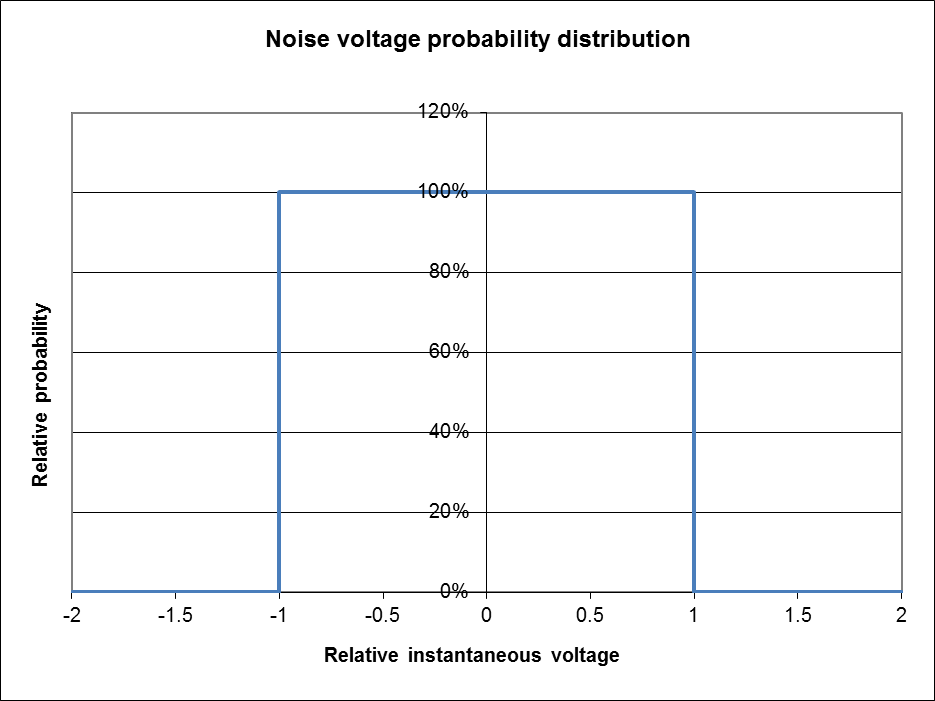
Fig 1 shows the probability distribution described by Smith ([t]he average
value of that noise voltage is zero because it is just as likely to be positive
as negative. It is also equally likely to be small as large
).
Importantly, the distribution has a discontinuity at +/-1 (+/-A in Smith's terms), and that discontinuity is difficult to explain in a natural system.
Smith derives the following relationships based on the distribution above:
Smith also discusses errors in using an AC voltmeter of a peak-reading
type calibrated as RMS
.
Referring to [o]ne may use these facts to compute the average and RMS
power of noise
, the correct terminology is that the RMS voltage can be used
to compute the average power (given Z), and vice versa.
In the context of determination of Noise Floor, Sensitivity, IP3 intercept and Blocking Dynamic Range, the noise component of receiver output power is predominantly due to white noise generated mainly in the source and receiver input circuit.
The power density of white noise is independent of frequency.
Though the noise might originally be created with white noise characteristic, it is usually bandwidth limited by later circuits in the receiver, and there is often amplitude/frequency variation across the nominal receiver pass-band (often designed in to cheat the Sensitivity test). Nevertheless, such noise is usually treated as white noise, rightly or wrongly.
One of the challenges in receiver testing is determination of receiver output power when the output is a complex waveform, eg comprised of both noise and one or more sinusoids.
Thermal noise is often thought of as due to random processes at molecular level, a result of thermal agitation of molecules and the associated rearrangement of charges.
This leads to the thought that the instantaneous voltage is a normally distributed random variable with mean of zero and some variance. So the only statistic that changes is the variance, a measure of the spread of the instantaneous values. (It can be shown that variance of noise voltage in a resistor is proportional to absolute temperature.)
The variance of a normally distributed random variable is defined as the mean of square of the deviation of each value from the distribution mean. In this case, since the mean of the distribution is zero, the variance is the mean of the square of the instantaneous values. The square root of the variance is the RMS value of the noise voltage.
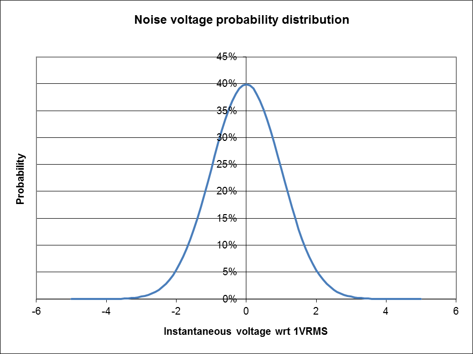 |
Fig 2 shows the probability distribution of a 1V RMS noise voltage if it is taken to be a normally distributed random variable. The distribution function is continuous over the whole range.
Importantly, as a normally distributed random variable, there is no upper or lower limit to the instantaneous value, it could be extremely high or extremely low, thought the probability of extreme voltages is very low (but NEVER zero).
Some important outcomes of the assumption that noise is a normally distributed random variable:
Smith refers to a peak reading voltmeter calibrated in RMS. He probably means an instrument that responds to peak voltage and is scaled in RMS for a sine wave.
A competent measurement technician understands the behavior of the instruments in use, and the use of any instrument to measure a complex wave raises the issue of accuracy since many are scaled to read accurately for a sine wave and may have significant error on complex waves.
Many AC voltmeters are of a type that charges a capacitor using a rectifier, and that voltage is applied to what is essentially a DC voltmeter. The issues that arise are how quickly the capacitor charges and how slowly it decays. Unless designed specifically to capture very short transients, these can at best be described as quasi peak responding instruments, and their response to a complex waveform like band limited white noise or band limited white noise + sinusoid cannot be simply predicted.
The most accurate way to measure output power is using an instrument that responds to average power of the complex wave.
One solution is an instrument that reads "true RMS voltage" and that has sufficient bandwidth for the complex wave. Further, the instrument should have a sufficiently long integration time to minimise the variation from one reading of same phenomena to another (due to the fundamental nature of noise, see (Duffy 2007)).
NFM provides facility to measure narrowband complex waves over quite long integration times.
(Allison et al 2011) uses a HP339A which has a true RMS voltmeter, though limited to crest factor <=3 which suggests it might clip some extreme peaks, but the error will be quite small (Duffy 2007b).
The following conclusions are drawn:
A search failed to turn up errata for (Smith 2002). ARRL has a practice of burying corrections if they are made in a "Technical correspondence" column which might not be publically available. The author has not been contacted as he was an ARRL staffer at the time, and the ARRL has never responded to this author's emails. There was no errata packaged with (Smith 2002) on the ARRL website.
| Version | Date | Description |
| 1.01 | 16/12/2012 | Initial. |
| 1.02 | ||
| 1.03 | ||
| 1.04 | ||
| 1.05 |
© Copyright: Owen Duffy 1995, 2021. All rights reserved. Disclaimer.