Some thoughts on filtering a PWM amplitude modulator
Background
The design under consideration is a FET Class E RF Power amplifier supplied from a modulated DC supply. The supply is pulse width modulated to vary the amplitude of the supply voltage to the PA and hence RF Power output, and so achieve Amplitude Modulation.
For discussion purposes, lets take the example of a PA that is operated over the range 0 to 80V at a peak current of 6.7A, Rl=12Ω.
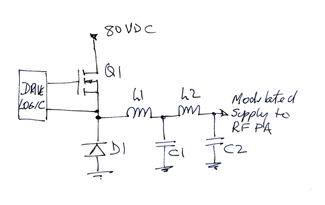 |
Fig 1 shows the circuit. Q1 is switched on and off by the drive logic. The pulse repetition frequency is fixed at 160kHz, and the duty cycle is varied in sympathy with the audio input voltage. The Drive logic must filter the audio to prevent aliasing, and converts the analogue audio wave form to a fixed frequency variable duty cycle rectangular wave.
The anti-aliasing requirement isn't too onerous since the audio bandwidth needs to be limited to 4kHz for licence compliance. Effectively, measures taken to limit audio bandwidth to 4kHz will deal with the aliasing issue.
This rectangular waveform contains spectral components at DC, audio frequencies, and higher frequencies around the pulse repetition frequency and its harmonics. The rectangular waveform cannot be directly applied to the RF PA because of this substantial energy at undesired frequencies.
The rectangular waveform is passed through a low pass filter formed by L1, C1, L2, C2 to reduce these undesired products.
Filter
In Australia, the Amateur LCD requires that spurious emissions be 50dB below the average desired signal power level.
Considering:
- the average power of a 100% modulated AM signal is 150% of the carrier, or 1.8dB above the carrier level;
- the level of one sideband of a 100% modulated AM signal is 6dB below the carrier;
then the level of one sideband of a 100% modulated AM signal is 7.8dB below the mean signal power.
The amplitude of the fundamental component of a square wave is 4/π times the amplitude of the square wave, or 2.1dB higher.
If the square wave is of sufficient amplitude to cause 100% modulation of the carrier, a 160kHz will be -7.8+2.1dB or -5.7dB relative to the mean power. This is 44.3dB short of the LCD requirement for spurious signals.
Let us set the filtering requirement to -55dB gain at 150kHz to allow some tolerance for filter design and to capture the spectral distribution the components around 160kHz under voice modulation.
A simple approximation is to consider that the load on this filter is a constant impedance of 12Ω. That is probably an acceptable approximation.
The driving impedance would be much lower, on half of the cycle it is the DC supply via the FET in saturation, and on the other half of the cycle, the flyback diode in saturation.
There are many different filter topologies that could be chosen. A simple filter would be a maximally flat low pass filter chosen to have 55dB of rejection at 150kHz.
Butterworth filter
The simplest approach would be a Butterworth filter for equal source and load impedances of 12Ω. It is easy to find the cut-off frequency for such a filter with say, four elements and gain of -55dB at 150kHz. The cut-off frequency would be 30.8kHz.
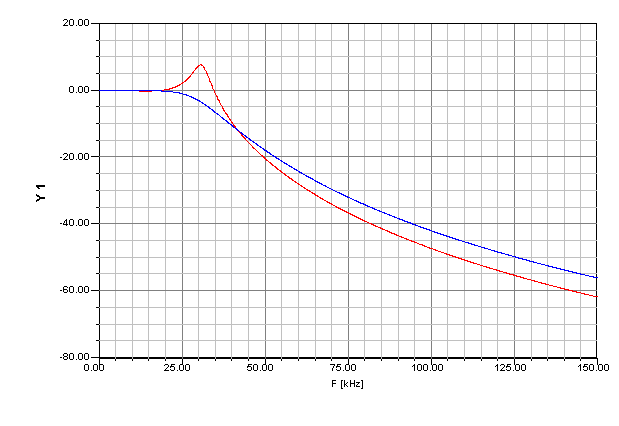 |
Fig 2 shows the filter response. The blue line is the filter with equal source and load impedances of 12Ω. The red trace shows the response when the source has zero impedance.
Although designing for equal impedances does not reflect the actual circuit, the filter remains flat over the 0 - 4kHz range and delivers higher rejection than required at 150kHz and so is conservative, and acceptable, albeit at the expense of requiring possibly larger inductors.
To achieve the design rejection, the filter should be implemented with minimal coupling between the inductors, and due consideration given to the ground current paths from C1 and C2. Note that low µ toroids such as these have appreciable magnetic leakage, and the cores should be oriented at 90º to each other.
A better approach is a filter designed to provide the desired response when voltage driven (ie low source resistance).
Maximally flat filter - Design tool
This section provides the information to design a maximally flat four element inductor input filter designed for unequal source and load impedances using a prototype developed using the filter wizard in Ansoft Designer.
The design parameters are:
- attenuation A in dB at frequency fA in Hz;
- load resistance (Rl);
- source impedance is zero; and
- ideal components (ie lossless inductors and capacitors, no parasitic capacitance etc).
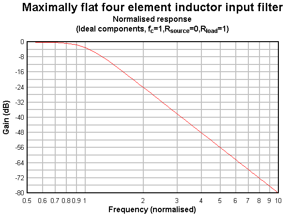 |
Fig 3 shows the normalised filter response.
| Quantity | Expression |
| fc (Hz) | (0.0002439+1.004*EXP(-0.02883*A))*fA |
| L1 (H) | 0.244/fc*Rl |
| C1 (F) | 0.252/fc/Rl |
| L2 (H) | 0.173/fc*Rl |
| C2 (F) | 0.061/fc/Rl |
Table 2 shows expressions for the filter design that are valid for values of A greater than 25dB. (The expression for fc depends on a fit to the response curve for gain < 25dB, or attenuation >25dB.)
Maximally flat filter - Example
This design if for a maximally flat filter with zero source impedance and load impedance of 12Ω. A 4 element filter with a cut-off frequency fc=30.9kHz delivers the required attenuation A= 55dB at fA=150kHz.
| Quantity | Value |
| A (dB) | 55 |
| fA (kHz) | 150 |
| Rl | 12 |
| fc (kHz) | 30.8 |
| L1 (µH) | 94.8 |
| C1 (µF) | 0.68 |
| L2 (µH) | 67.2 |
| C2 (µF) | 0.16 |
Table 3 shows the results for the example problem.
To achieve the design rejection, the filter should be implemented with minimal coupling between the inductors, and due consideration given to the ground current paths from C1 and C2. Note that low µ toroids such as these have appreciable magnetic leakage, and the cores should be oriented at 90º to each other.
Inductors
The inductors in this case have inductances in the range of 100µH, and will carry currents of up to 7A.
To minimise the size of the inductors, some kind of high permeability core is a candidate. Saturation is a key issue in this application.
It turns out that ferrites saturate at a magnetic field strength of the order of 100A/m. Considering a toroidal core of effective path length of less than 100mm, this corresponds to a MMF of less than 10At, which at 7A limits the number of turns to 1t. A ferrite core is not going to be suitable. An air gap could be used to reduce the magnetic field strength in the core, but it isn't very practical for a toroid of this type / size.
Iron powder cores have lower permeability, but much higher saturation field strength.
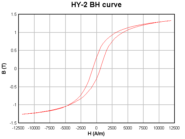 |
Fig 4 shows the B-H characteristics of the HY-2 material used in a range of powdered iron cores sold by Jaycar. µ is specified as 75.
Applied to the Jaycar LO1244 28x14x11mm powdered iron core and designing to stay well below saturation , degrading µ by 80% to allow for the effect of the DC bias, an Al value of around 92nH/t2 is calculated.
| Component | L (µH) | turns | Hdc @ 3.5A (A/m) |
| L1 | 95 | 32 | 1776 |
| L2 | 67 | 27 | 1495 |
Table 4 shows values for a Jaycar LO1244 28x14x11mm powdered iron core which cost about A$2.20 each. The ID of this core is 14mm, so it will comfortably accommodate the required number of turns, and magnetic field strength is well below saturation.
| Component | L (µH) | turns | Hdc @ 3.5A (A/m) |
| L1 | 95 | 24 | 1730 |
| L2 | 67 | 20 | 1457 |
Table 5 shows values for the larger Jaycar LO1246 42x22x17mm powdered iron core which cost about A$10.00 each which may better suit wire with thicker insulation. The ID of this core is 17mm, so it will comfortably accommodate the required number of turns, and magnetic field strength is well below saturation.
Magnetics are design challenges. Vk3AIY has built and tested the LO1246 implementation.
Capacitors
C1 and C2 are 0.68µF and 0.16µF respectively. These capacitors will carry substantial current and should be selected for that use. Note that RF bypassing in the PA appears in parallel with the output of the filter, and should be considered as part of C2.
Practical filters
Practical components are not ideal, for example they have losses and inductors have self resonances as a result of distributed reactance, circuit elements are coupled by stray capacitance and inductive coupling. These imperfections limit to the attenuation achievable in a practical circuit.Some key points:
- choosing a low cut-off frequency requires larger inductances which have lower self resonances, limiting the filter's high frequency attenuation;
- fewer elements drives lower cut-off frequency;
- inductors should be designed to minimise self capacitance;
- screening and physical isolation are important to achieving high attenuation;
Conclusions
Powdered iron cores have high saturation field strength and are well suited to high power applications.
Ferrite cores are probably not suited to high power applications because of lower saturation magnetic field strength. An air gap could be used in some types of ferrite cores to increase the saturation flux density.
This article has discussed filtering of the modulated supply to the RF PA. The DC supply will also require filtering to prevent conduction of switching components on the mains supply conductors.
11/07/09 18:12:22 -0600