 |
| OwenDuffy.net |
|
| This article is a review of the basics of noise and receiver performance. |
Noise is any undesired energy that interferes with a desired signal. Noise sources include:
Noise is inherent in all electric / electronic circuits and the noise limits the smallest signals that can be distinguished from the noise.
Internal noise can be divided into three categories:
Noise is generated in a resistor as a result of thermal agitation of electrons in the resistor. This is also known as Johnson noise. The noise power density is dependent on the temperature of the resistor, and the total noise power is a given bandwidth is dependent on temperature and bandwidth.
Pn=kb*T*B where kb is Boltzmann's constant (kb=1.3806504×10⁻²³ joule/kelvin) and T is the absolute temperature of the resistor in K.
Shot noise is noise due to random fluctuations in current flowing in a circuit due to discrete current carriers and exists in all electronic amplifying devices. Shot noise is quite predictable in a thermionic diode in temperature limited emission, but it is not as well predicted in other types of active devices.
Frequency dependent noise occurs at extremely low frequencies and at the upper limit of useful frequency for some active devices which is usually of little consequence in receivers.
An amplifier can be represented by an ideal amplifier with an equivalent input noise source. The equivalent input noise source could be expressed as an equivalent noise resistance, an equivalent noise temperature, or equivalent noise voltage to name a few of the more common equivalences.
Noise Factor (nf) is a measure of the way in which a system component degrades the Signal/Noise ratio. It is the ratio of S/Nin to S/Nout.
nf=(Sin/Nin)/(Sout/Nout)
Noise Figure (NF) is Noise Factor expressed in dB.
NF=10*log(nf).
Noise Temperature (or more correctly Equivalent Noise Temperature) Te is ...
Te=290*(nf-1)
Te=290*(10^(NF/10)-1)
Noise temperature is proportional to power, the total noise temperature of two or more noise sources combined is the sum of the noise temperature of all of the sources.
 |
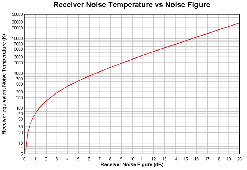
Fig 1 shows the relationship between receiver Noise Figure (dB) and equivalent Noise Temperature (K).
For example, a receiver with a noise figure of 0.7dB has the same internal noise as an ideal receiver with a matched input resistance at 51K.
The Noise Figure of a matched attenuator is the same as its attenuation in dB.
The Noise Temperature of a matched attenuator is 290*(10^(A/10)-1) where A is its attenuation in dB.
The gain of a matched attenuator is the ratio of output power to input power or 10^(-A/10) where A is its attenuation in dB.
For example, Te for a 0.5dB loss (or attenuator) is 35K, and its Gain is 0.891.
The Noise Temperature of two stages in cascade is given by Friis' formula:
Te= Te1+ Te2/G1 where G is the Gain of a stage.
This expression can be expanded for an arbitrary number of stages by successively replacing Te2 with the expression for a cascade of two stages. For example, for two stages:
Te= Te1+ (Te2+ Te3/G2)/G1 which becomes Te= Te1+ Te2/G1+ Te3/G2/G1
An expression can similarly be written for NF by substituting for Te, but it is so complex that it tends to hide the simplicity of what is happening.
For example cascading a line loss of 0.5dB with a receiver of NF=0.7dB gives Te= 35+ 51/0.891=92K, system NF=10*log(92/290+1) = 1.2dB
The environment external to the receiving system is a source of noise. Sources include galactic noise, man-made noise and atmospheric noise. The level of the noise is dependent on frequency, time and location.
The ambient noise level is often expressed as a Noise Figure in dB or as an equivalent Noise Temperature in K. It is the noise power wrt the noise in a matched resistor at room temperature (taken as 290K).
 |
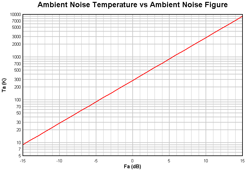
Fig 2 shows the relationship between ambient Noise Figure (Fa) and ambient noise temperature (Ta).
For example, an ambient Noise Figure of 6dB is an ambient Noise Temperature of 1155K.
Note that the radiation resistance of an antenna is not a resistor and not a source of kb*T*B noise.
To properly understand the performance of a receiving system, it must be analysed as a system that includes ambient noise, preamplifiers and main receivers, and interconnecting cables and components. The system noise floor can be calculated using the principles discussed above. The system noise floor is equivalent to the signal level for a S/N ratio of 1.
 |
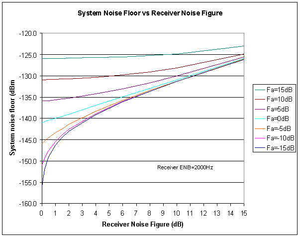
Fig 3 shows the relationship between system noise floor and receiver noise figure for a range of ambient noise figures. The system noise floor is the total noise power from all sources.
Low receiver noise figure is of most benefit in low ambient noise, indeed in a high ambient noise environment, reducing receiver noise figure makes very little difference to the system noise floor.
For example, if Fa is 10dB, reducing receiver noise figure from 8dB to 0.5db (eg using a low noise preamp) reduces the system noise floor by just 1.8dB.
 |
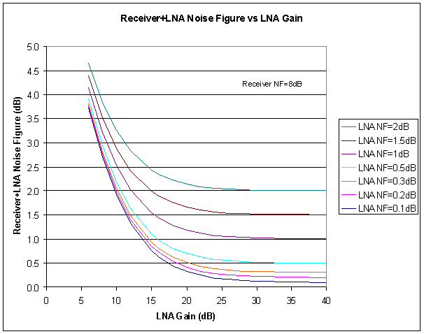
Fig 4 shows the effect of LNA gain on Receiver+LNA Noise Figure in a simple model that has zero loss between the LNA and receiver. The full benefit of the LNA's NF can only be realised if the LNA has sufficient gain to make the receiver noise temperature contribution to the total noise temperature insignificant. More gain make only a minor improvement to Receiver+LNA Noise Figure.
Real receiving configurations are more complex, and the full implications of configuration options can only be understood by developing a configuration model to calculate the performance of the various scenarios. A framework for such modelling and a modelling tool is given in the article Effective use of a Low Noise Amplifier on VHF/UHF .
1. A 2kHz wide SSB receiver with NF=6dB is connected to an impedance matched antenna (1dB of line loss) and tuned at about 144Mhz to a frequency where there is only ambient noise heard and no AGC action. The audio output voltage is measured as 200mV. The antenna is then replaced with a dummy load and the audio output voltage is measured as 143mV. What is the apparent ambient noise temperature and ambient noise figure?
Obtain Te for the 1dB attenuator and 6dBNF receiver from Fig 1, they are 75K and 865K respectively. The gain of a 1dB attenuator is 0.794, so the cascaded line loss and receiver have a Te of 75+865/0.794K or 1163K. With the dummy load attached to the system input, the total input noise temperature is 290+1163K or 1453K which causes 143mV audio output.
The total input noise temperature to cause 200mV audio output must be (0.200/0.143)^2*1453K or 2843K. Deducting the cascaded line loss and receiver Te of 1163K, ambient noise temperature Ta is 1680K. The ambient noise figure Fa from Fig 2 is 7.6dB.
2. What is the system noise floor?
From Fig 1, the system noise figure for Te of 1163K is 7dB. From Fig 2, the noise floor for a 2kHz wide receiver is -131dBm.
(This example depends on the linear relationship between audio output power and input power of an SSB receiver at signal levels less than the AGC threshold.)
| Term | Meaning |
| dB | decibel - power ratio |
| dBm | decibels power wrt 1 mW |
| ENB | Effective Noise Bandwidth |
| Fa | Ambient noise figure |
| FET | Field Effect Transistor |
| G/T | Gain to Noise-temperature ratio |
| IMD | Inter Modulation Distortion |
| LNA | Low Noise Amplifier |
| RFI | Radio Frequency Interference |
| SINAD | signal-plus-noise-plus-distortion to noise-plus-distortion ratio |
| SSG | Standard Signal Generator |
| S/N | Signal to noise ratio |
| VOX | Voice operated switch |
| Version | Date | Description |
| 1.01 | 10/06/2007 | Initial. |
| 1.02 | ||
| 1.03 |
Use at your own risk, not warranted for any purpose. Do not depend on any results without independent verification.
© Copyright: Owen Duffy 1995, 2021. All rights reserved. Disclaimer.