 |
*** DRAFT ***
This article describes a WiFi connected remote relay controller implemented using a ESP12F_Relay_30A X4 board.
|
|
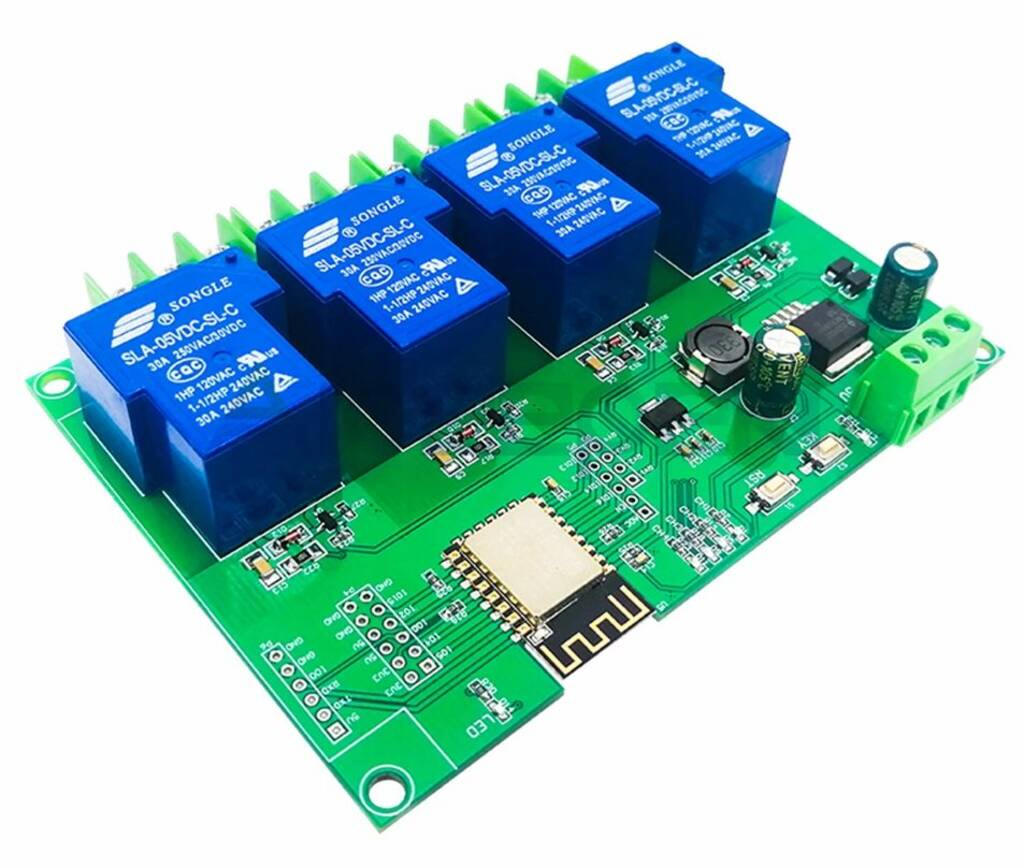
Fig 1 shows the top side of the module. The SM regulator is a LM2596 on this board.
Datasheets are availble online for the SLA relay. Though rated at 30A, that is for resistive loads, its motor rating is 1HP, 16A. The relay has 1xC form contacts, single pole with NO and NC contacts.
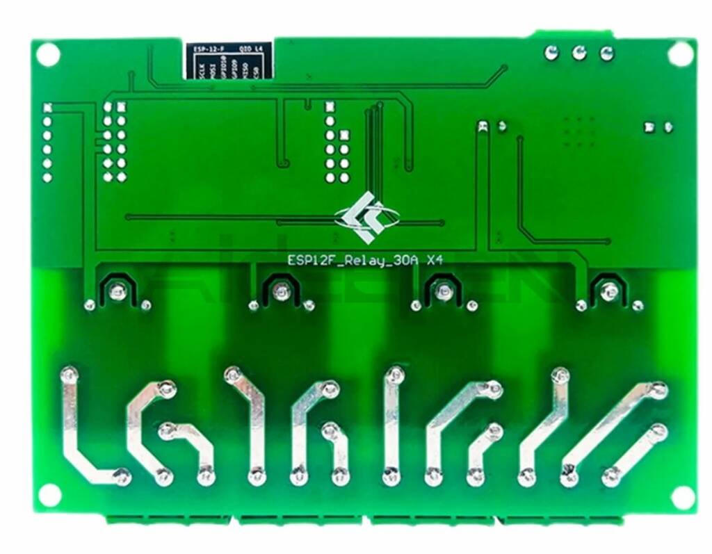 |
Fig 2 shows the under side of the module after resolding a couple of pins, removing solder splashes from manufacture, inserting the header pins, cleaning the flux and a heavy coat of clear acrylic PCB lacquer. This stuff is Chinese Quality, you need to go over it with a magnifier... especially in areas subject to mains voltage. This is actually a fairly good board design, lots of distance between the relay tracks.
There is lots of programmer hardware that may suit, this article describes two options.
See WiFi relay controller - ESP12F_Relay_30A X2_V1.1 for application of the ESP01S programmer to the 2 channel board. The connections to this board are the same, but the row of header pins is moved as can be seen in the following section.
ESP-Prog is from Espressif.
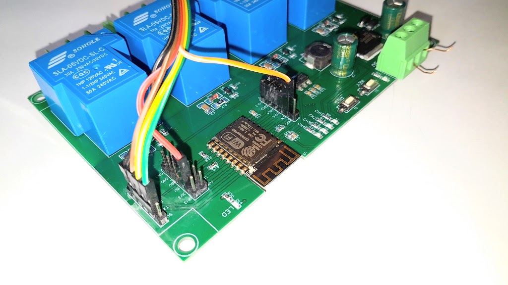 |
Fig 7 shows board connections.
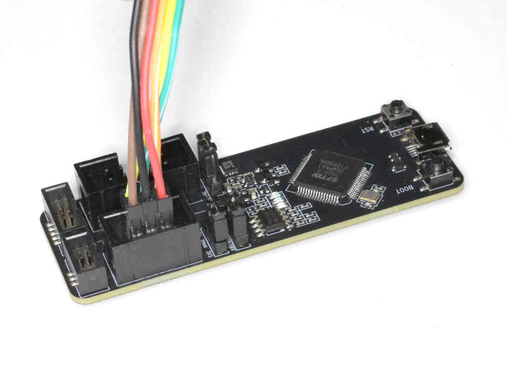 |
Fig 8 shows an ESP-Prog costing <$25 online and incorporating the auto program circuit. The above module has a FTDI chip and contains the auto program circuit. The pic shows individual jumpers (ie 6 x 1W), but you can extract the pins and fit them to a 6W shell for convenience (as I did after the pic).
Configuration is read from file config.json in the LittleFS on-board file system.
Example config file:
{
"cfgver": 1,
"wifi": {
"ssid": "",
"pwd": ""
},
"staticip":{
"address":[0,0,0,0],
"mask":[255,255,255,0],
"gateway":[192,168,0,20]
},
"hostname": "EspRelay-4x30A",
"login": {
"user": "",
"pwd": ""
},
"outputs": [
["RY1",16,false,false],
["RY2",14,false,false],
["RY3",12,false,false],
["RY4",13,false,false]
],
"inputs": [
["IN1", 5, false, true],
["IN2", 2, false, true],
["IN3", 0, false, true],
["IN4", 15, false]
],
"wificfgpin": 4
}
The config above uses IO4 which is connected to the KEY press button to activate WiFi configuration mode on boot.
|
|
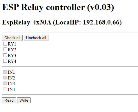
Fig 7 shows the web form for interacting with the controller (this example is for the 2 relay board).
With four relays operated, it draws 330mA @ 13.8V. The board contains a SMPS which does not seem to have serious RF emissions.
| Version | Date | Description |
| 1.01 | 08/04/2022 | Initial. |
| 1.02 | ||
| 1.03 | ||
| 1.04 | ||
| 1.05 | ||
| 1.06 | ||
| 1.07 | ||
| 1.08 |