 |
| OwenDuffy.net |
|
*** DRAFT ***
This article describes a WiFi connected remote relay controller implemented using a WiFi relay controller - LilyGo-T-Relay board.
|
|
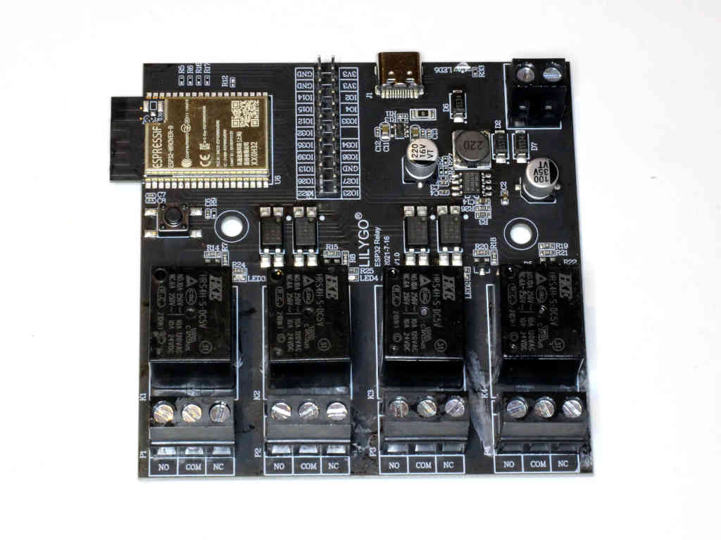
Fig 1 shows the top side of the module.
Datasheets are availble online for the HRS relay. Though rated at 15A, that is for resistive loads. The datasheet does not give a rating for motors or other inductive loads, in that cases it is probably unwise to use it above 5A for such loads. The relay has 1xC form contacts, single pole with NO and NC contacts.
Note the connector on the top edge of the board, it is a USB-C connector but is it NOT intended for USB-C use, it is not a USB-C device, and plugging a cable between that connector and a PC USB-C port may well cause damage to one or both. A really silly idea IMHO. There is a USB-C adapter available, it is discussed later.
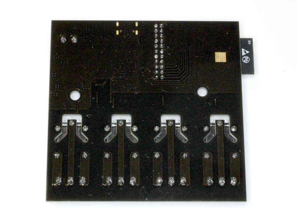 |
Fig 2 shows the under side of the module after inserting the header pins, cleaning the flux and a heavy coat of clear acrylic PCB lacquer.
This board is a reasonably good design, good track separation and routed out to reduce the risk of tracking where large separation was not an option. As boards go, it is above average.
There is lots of programmer hardware that may suit, this article describes one option.
This programmer is designed and sold for the LilygOtarget, it is quite cheap (<$10 shipped) and quite convenient for this project.
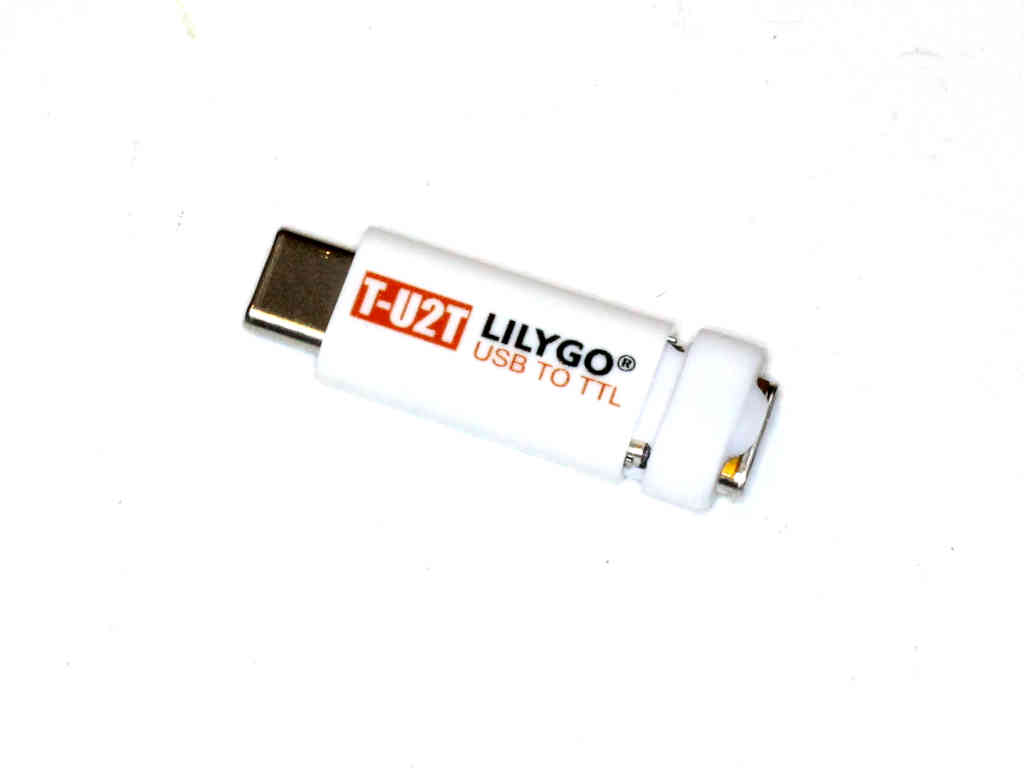 |
Fig 1 shows an improved programmer for the LilyGo T-U2T costing <$10 online (if purchased with the relay board) and incorporating the auto program circuit. The above module has a CH9102 USB chip and contains the auto program circuit.
Example config file:
{
"cfgver": 1,
"wifi": {
"ssid": "",
"pwd": ""
},
"staticip":{
"address":[0,0,0,0],
"mask":[255,255,255,0],
"gateway":[192,168,0,20]
},
"hostname": "LilyGo-TRelay",
"login": {
"user": "",
"pwd": ""
},
"outputs": [
["K1",21,false,false],
["K2",19,false,false],
["K3",18,false,false],
["K4",5,false,false]
],
"inputs": [
["GPIO 21 K1",21,false],
["GPIO 19 K2",19,false],
["GPIO 18 K3",18,false],
["GPIO 6 K4",5,false],
["GPIO 12 (9)",12,false],
["GPIO 32 (11)",32,false],
["GPIO 35 (13)",35,false],
["GPIO 39 (15)",39,false]
]
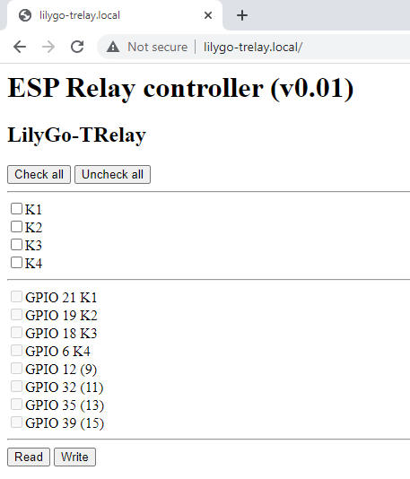
}For test purposes, the relay outputs are configured as inputs, and a further four GPIO pins wired to headers.
|
|
Fig 7 shows the web form for interacting with the controller.
The DC input is rated at 12-24V. With both relays operated, it draws 150mA @ 13.8V. The board contains a SMPS which does not seem to have serious RF emissions.
| Version | Date | Description |
| 1.01 | 09/04/2022 | Initial. |
| 1.02 | ||
| 1.03 | ||
| 1.04 | ||
| 1.05 | ||
| 1.06 | ||
| 1.07 | ||
| 1.08 |
© Copyright: Owen Duffy 1995, 2021. All rights reserved. Disclaimer.