 |
| OwenDuffy.net |
|
This article lists the contents of the Roger Beep kit and contains notes and information for constructors.
| Designator | Value | Notes |
| C1, C2 | 0.001 | |
| C3, C4, C5 | 1 | |
| D1 | 1N751 | |
| PCB | RBv1.1 | |
| Q1 | 2N7000 | |
| R1, R5 | 12k | |
| R2, R3 | 1k0 | |
| R4 | 470 | 1 |
| R6 | 0 | 2 |
| R7 | 10k | |
| R8 | 6k2 | |
| R9 | 3k9 | |
| U1 | Programmed PIC12F629-I/P | |
| VR1 | 500 | 4 |
Table 1 is a list of parts that are supplied in the kit.
Notes:
|
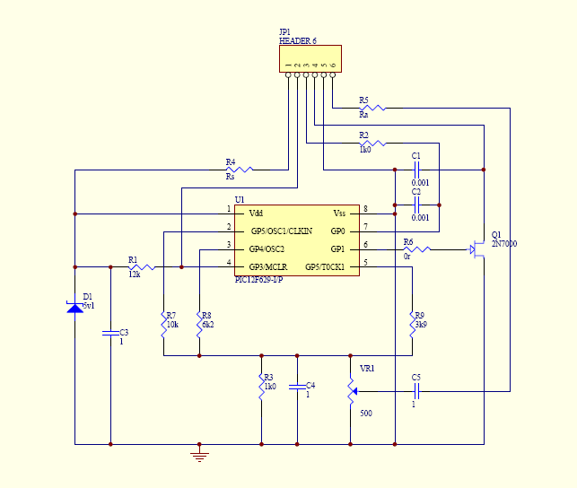
Fig 1 shows the RB circuit diagram.
| Pin | Description |
| 1 | +DC |
| 2 | Reset (NC) |
| 3 | PTT in (from mic) |
| 4 | PTT out (to transmitter) |
| 5 | Ground |
| 6 | Audio out |
Table 2 shows the usage of pins on JP1. Most constructors will wire directly to the PCB, but for those who wish to use a connector, a normal 6 pin polarised header plug, or 90° version of same can be installed on the board.
Note that PTTin is for connection of a PTT switch that provides a contact closure to ground to transmit. Check your connections carefully and DO NOT ATTEMPT TO USE IT IN ANY OTHER WAY.
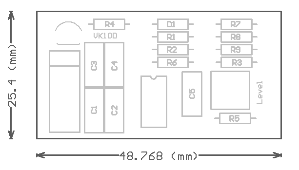 |
Fig 2 is a view of the parts overlay. The cathode (ie the stripe) of D1 goes to the left.
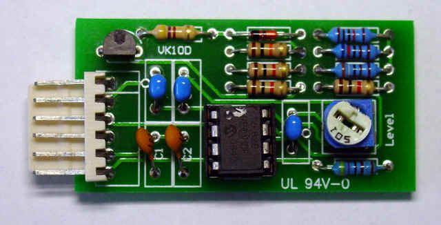 |
Fig 3 is a view of the component side of a board using an optional 90° 6 pin polarised header. The chip was socketed in this case because this RB is used to test program code. Constructors could optionally install a socket to facilitate chip upgrade. R6 on this board has a 1k0 resistor installed, constructors would normally use a wire link, and R5 on this board is 4.7K to suit the transceiver.
Shielded wire should be used from JP1 pins 5 and 6 for the audio connection.
| Version | Date | Description |
| 1.01 | 23/12/2007 | Initial. |
| 1.02 | ||
| 1.03 | ||
| 1.04 |
© Copyright: Owen Duffy 1995, 2021. All rights reserved. Disclaimer.