 |
| OwenDuffy.net |
|
*** DRAFT***
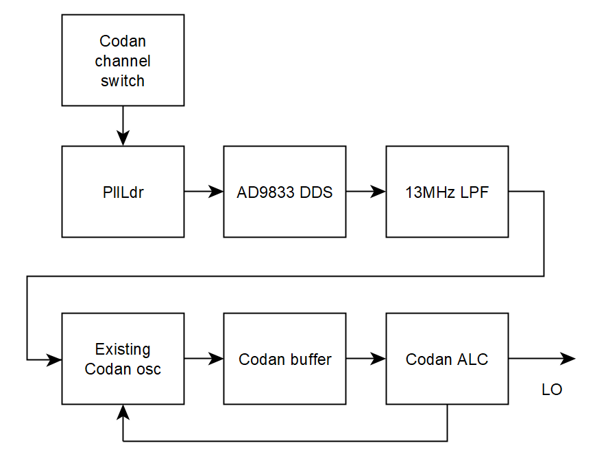
The Codan 6924 is an older SSB transceiver using a single crystal per simplex SSB channel, for up to 10 channels. The channel switch selects the crystal oscillator and also a band pass filter for that channel.
This article describes an application of PllLdr / PllLdr2 to an AD9833 DDS as a crystal replacement in the Codan 6924 transceiver for ham bands. The objective was an internal replacement for crystals which are quite expensive, compatible with the existing architecture and using the existing controls. Note that the modification would compromise type approvals.
|
|
Fig 1 shows a block diagram of the crystal replacement and its integration with the existing electronics.
PllLdr is available on several chips, the most relevant for this project are an ATTiny44 which allows 8 channels, or an ATMega328P which allows all 10 channels. The Atmega328P is conveniently implmented by using an inexpensive Arduino Nano 16MHz/5V module (more later). For this initial project, the ATTiny44 was used.
The transceiver provides 10 wires for crystal selection, on is raised to around 11V to select. Some of these signals are used as inputs to PllLdr, but they must be reduced to below 5V. Datasheet states chip pullup R=20-50k. On 5V, Imax=5/20k=250uA, so, for 0.3V input, R=0.3/250e-6=1.2k. The high side R from 11V twice that, 2k2, so you would get 1/3.2*11=3.4V for a high. This sinks 3mA of current, but only on one active channel circuit.
Now the ATTiny supports 7 input pins (sel[0]-sel[6]), so wire them CH1-sel[0] which selects EEPROM address 1 through CH7-sel[6] which selects address 7, no input (CH8-CH10) selects address 0 so CH8-10 will select the same channel (the one at EEPROM address 0) so tune those filters for that frequency.
If you use the ATMega328P (Nano), you have one input available for each of the 10 channels, but note that the corresponding EEPROM addresses are 1-10, 0 is allocated but unused. You could also use a ProMini, but not all pins of interest appear on the SIL edge headers and it lacks the integrated USB adapter for programming.
This article uses the Nano.
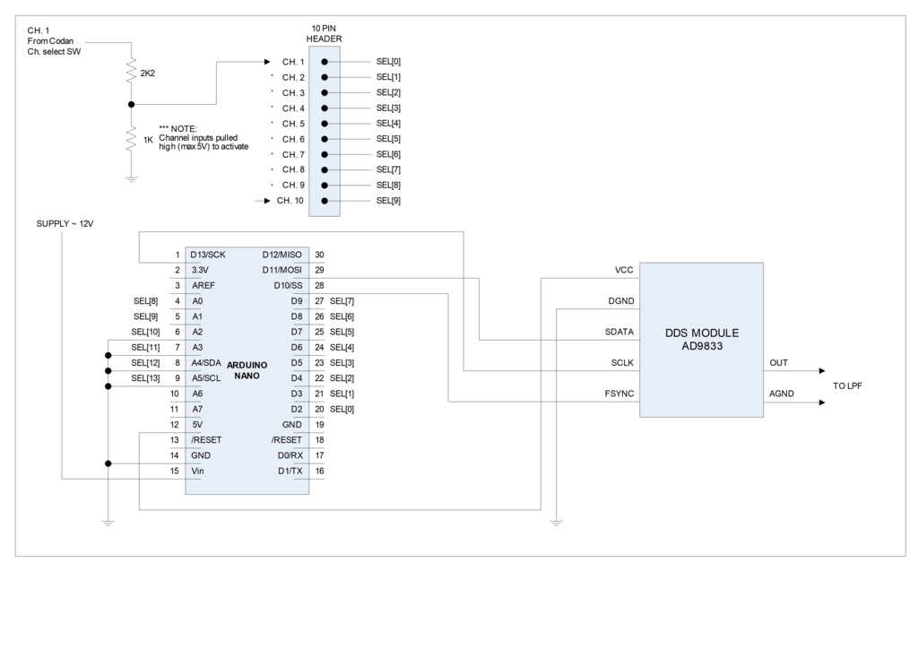 |
Fig 2 shows the schematic diagram.
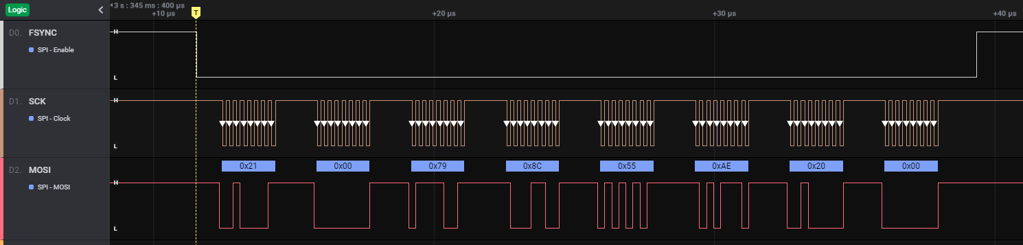 |
Fig 3 shows the SPI traffic for a frequency change.
The DDS used is a low cost chip that can be purchased online as a module with on board 25MHz reference oscillator for under $10. DDS output needs to be passed through a low pass filter to reject spurious products such as alias outputs.
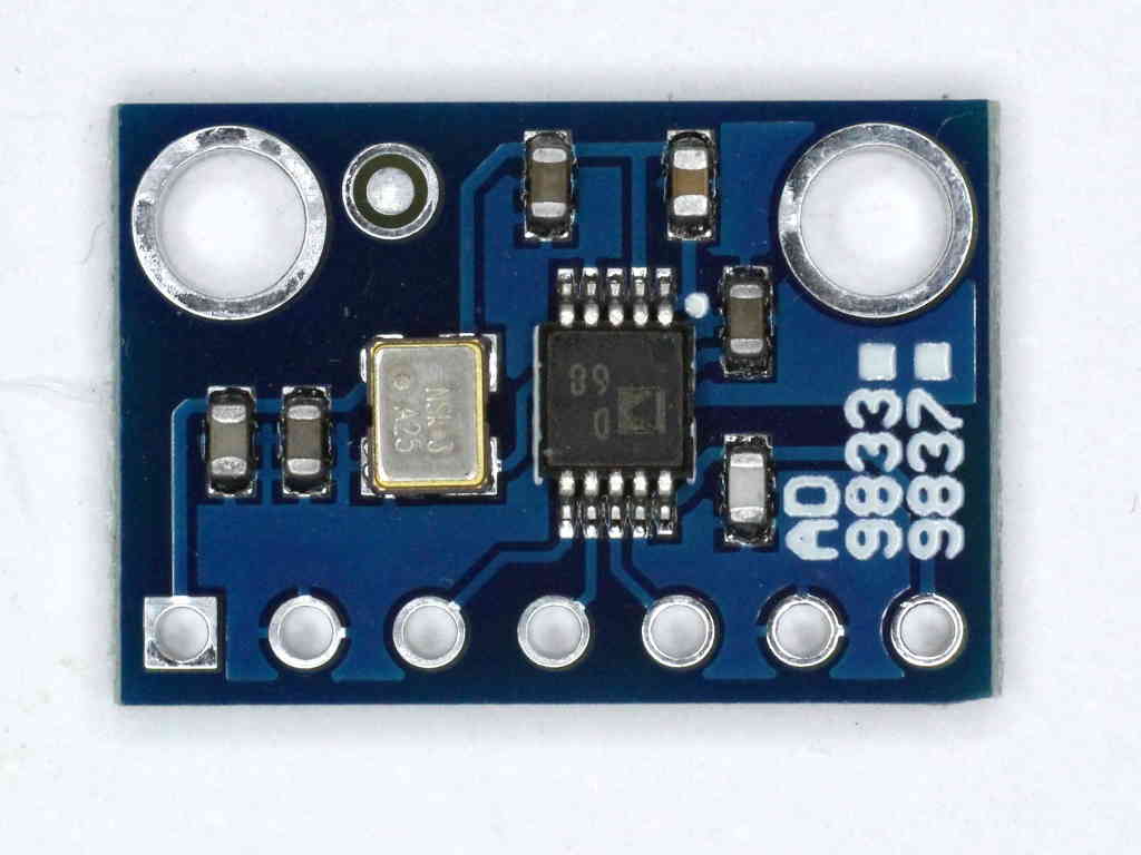 |
Fig 4 shows an example AD9833 DDS module.
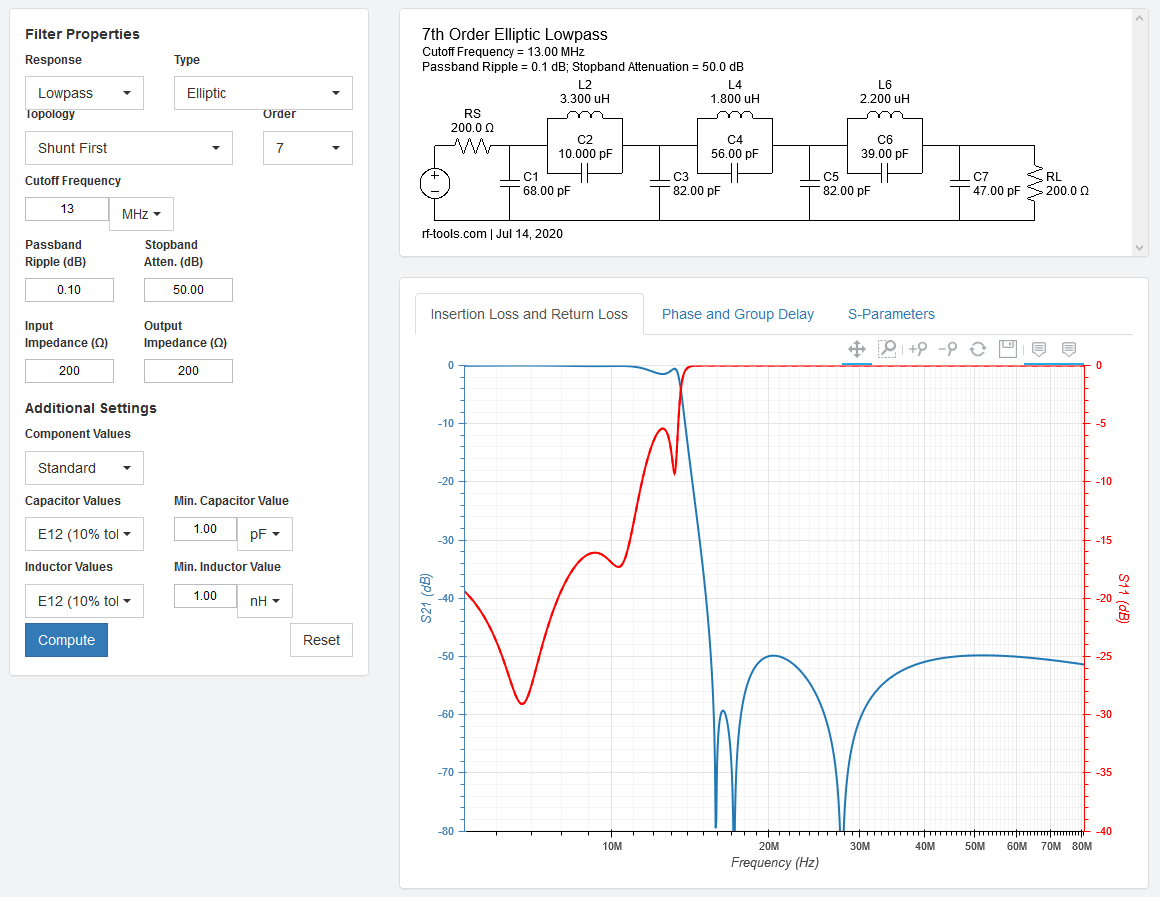 |
Fig 5 shows the 7 pole eliptic (Cauer / Zolaterev) low pass filter design. The design uses readily available inexpensive E12 series capacitors, and the inductors can be hand wound on inexpensive T25-1 powdered iron cores.
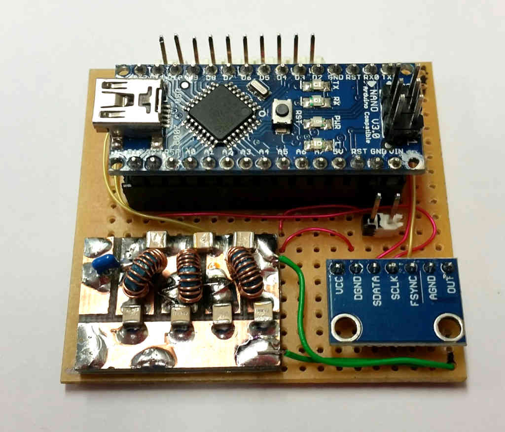 |
Fig 6 shows the small module on prototype board carrying the ATTiny44 MCU, AD9833 module and low pass filter. A SIL male header row behind the Nano is for the channel switch connections.
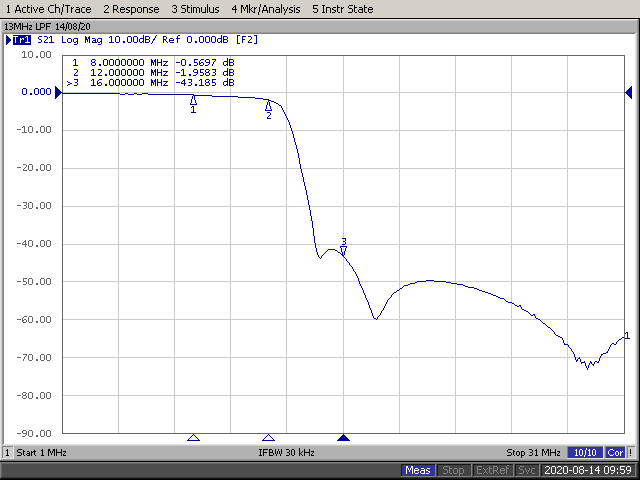 |
Fig 7 shows the measured response of the LPF constructed using T25-1 cores and high quality ATC capacitors
| watch this space |
Fig 6 shows the small module on prototype board carrying the ATTiny44 MCU, AD9833 module and low pass filter. The channel signals are picked up from the resistive dividers at left and fed to a SIL header connector on the DDS board. The output from the DDS board LPF is fed to the original crystal oscillator input and a 200Ω resistor provides the required termination of the low pass filter.
In this radio, only the first eight channels were fitted with bandpass filters, so it can only be equipped with eight channels.
| watch this space |
Fig 7 shows the front panel labelled for the channels. Readers will note that this radio also has the optional RF Gain control fitted.
The register values to be loaded into the AD9833 were calculated in a spreadsheet.
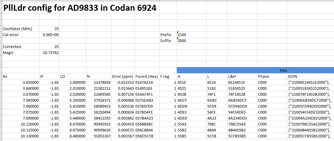 |
Fig 8 is a screen shot of the spreadsheet used to calculate AD9833 register values for each channel. The first entry is unused. The error of the 25MHz reference oscillator was measured and incorporated into the calculations for better channel accuracy... so the values are specific to THIS oscillator.
The following is an example EEPROM configuration in JSON format for input to the converter.
//JSON syntax does not provide comments, filter this file through jsmin to
//strip comments
/*************************************************
EEPROM data file for AD9833 for lunchbox radio - low side osc
OD 20200720
OFF
3.650000
3.660000
3.670000
7.045000
7.060000
7.075000
7.090000
10.120000
10.125000
10.130000
*************************************************/
//options: invert SCK, 1/17
{
"ver":"02",
"rbo":"",
"options":["8020","0000"],
"regs":[
["2100"],
["21006E14451E2000"],
["2100518345252000"],
["210074F1452B2000"],
["21006AB34DCF2000"],
["21005FD94DD92000"],
["210054FE4DE32000"],
["21004A234DED2000"],
["2100798C55AE2000"],
["21004B4455B22000"],
["21005CFB55B52000"]
]
}
Above is an example EEPROM configuration file for a 10 channel transmitter.
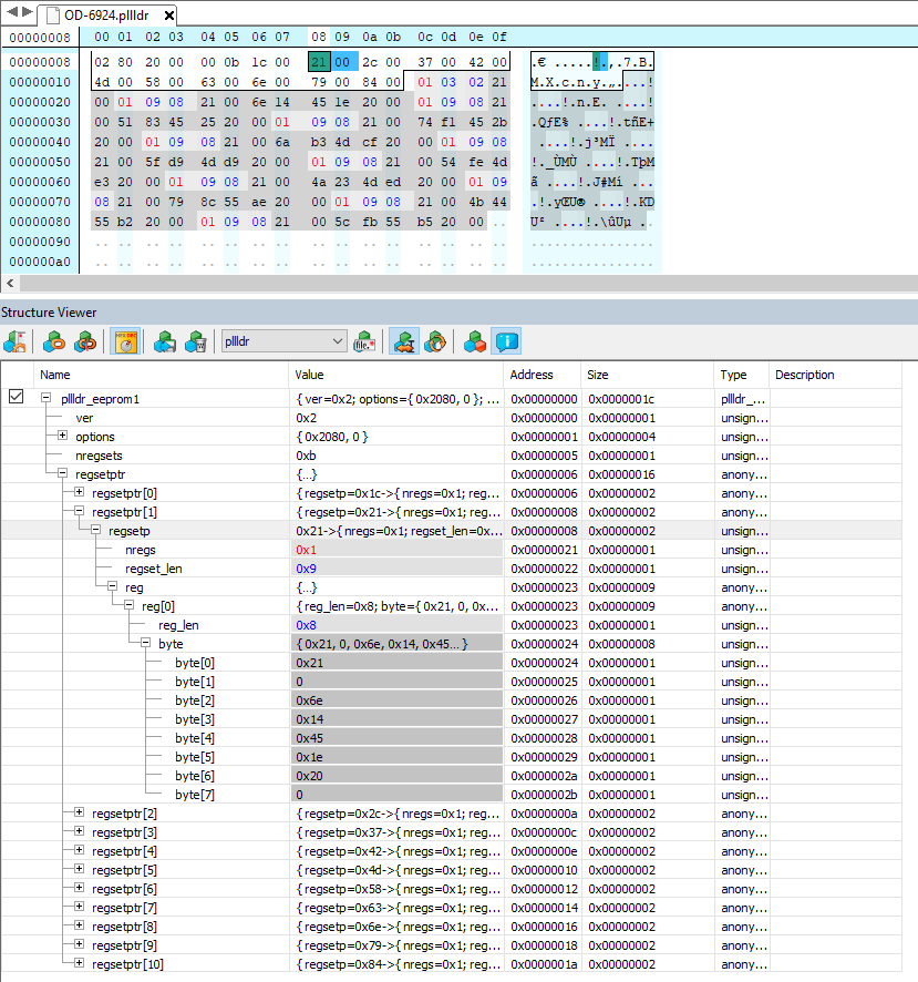 |
Fig 9 shows the binary EEPROM image structure. The screenshot is from HHD Hex Editor Neo Ultimate using its structure viewer.
Arduino Nano comes with an Optiboot bootloader that is unable to write to EEPROM, so we will replace it with a build of Optiboot that does support EEPROM. The bootloader occupies the top 1024B of flash, so it requires different fuse settings to the standard bootloader.
The command file below will load the modified Optiboot (link below) and set the fuses and locks using an inexpensive USBASP programmer... but you need to review it and change some default file paths.
@echo off

echo.
echo Processing
echo.
set FL=
if *%FL%==* set FL=d:\src\optiboot\optiboot\bootloaders\optiboot\optiboot_atmega328E.hex

echo FL=%FL%
set PRG=usbasp
set PORT=usb
rem set OPTS=-b 115200
set OPTS=-B 10
set DEVICE=atmega328p
set AVRDUDE=avrdude
rem preserve EEPROM
rem EFUSE=0x06 for 1.8V BOD, 0x05 for 2.7V
set EFUSE=0x05
set HFUSE=0xD4
set LFUSE=0xFF

:flash
echo.
echo Write boot loader (%FL%)...
echo.


echo %AVRDUDE% %OPTS% -c %PRG% -P %PORT% -p %DEVICE% -e -Ulock:w:0x3F:m -Uefuse:w:%EFUSE%:m -Uhfuse:w:%HFUSE%:m -Ulfuse:w:%LFUSE%:m
%AVRDUDE% %OPTS% -c %PRG% -P %PORT% -p %DEVICE% -e -Ulock:w:0x3F:m -Uefuse:w:%EFUSE%:m -Uhfuse:w:%HFUSE%:m -Ulfuse:w:%LFUSE%:m
timeout /nobreak /t 1 >nul
echo %AVRDUDE% %OPTS% -c %PRG% -P %PORT% -p %DEVICE% -U flash:w:%FL%:i -Ulock:w:0x0F:m
%AVRDUDE% %OPTS% -c %PRG% -P %PORT% -p %DEVICE% -U flash:w:%FL%:i -Ulock:w:0x0F:m
goto cleanup

:cleanup
echo.
:end
pause
Once installed (one off), application programming of flash and EEPROM is done using the Nano USB port and bootloader, example later.
The following is an example command file for programming application flash and EEPROM using AVRDUDE and bootloader using the USB port on the Nano. Note that some defaults need adjustment to suit your own environment.
@echo off
if *%1==* goto usage

echo Processing %1
echo.

set PRG=arduino
set DEVICE=m328p
set PORT=com7
if *%PORT%==* set PORT=COM7
set OPTS=-b 115200
set AVRDUDE=avrdude

if *%2==* goto eeprom
if *%2==** goto eeprom
set FLASH=%2
if *%2==*# set FLASH=D:\src\PllLdr2\PllLdr2\Release\PllLdr2.hex

echo program flash (%FLASH%)...
echo %AVRDUDE% %OPTS% -c %PRG% -P %PORT% -p %DEVICE% -U flash:w:"%FLASH%":i
%AVRDUDE% %OPTS% -c %PRG% -P %PORT% -p %DEVICE% -U flash:w:"%FLASH%":i
timeout /nobreak /t 1 >nul

:eeprom
if *%1==** goto cleanup
echo program eeprom (%1)...
echo %AVRDUDE% %OPTS% -c %PRG% -P %PORT% -p %DEVICE% -U eeprom:w:"%1":i
%AVRDUDE% %OPTS% -c %PRG% -P %PORT% -p %DEVICE% -U eeprom:w:"%1":i
timeout /nobreak /t 1 >nul
goto cleanup

:usage
echo usage: %~n0 eepromfile flashfile
goto end

:cleanup
set PORT=
:end
Credit to Bruce Boardman (VK4MQ) for the construction / implementation work and some pics and schematic.
| Version | Date | Description |
| 1.01 | 25/07/2020 | Initial. |
| 1.02 | ||
| 1.03 | ||
| 1.04 | ||
| 1.05 |
© Copyright: Owen Duffy 1995, 2021. All rights reserved. Disclaimer.