QRP antennas

We see more and more reference to “QRP antennas” online these days, and it begs the question, what makes an antenna more or less suited to QRP.

To a novice, the obvious possibilities for a low power antenna system are that they are:

  1. highly efficient to offset the lower power; and/or
  2. unable to withstand higher power.

Continue reading QRP antennas

Trial of prototype stand alone GPS logger

An upcoming project calls for a stand alone GPS logger.

The requirement is for a GPS stream that allows correction using RTKLIB, but this trial is of a lesser GPS as proof of concept.

SAGPS001

Above, the equipment consists here of a Ublox NEO-6M based GPS module (~A$15 incl on eBay) at left, an Openlogger (~A$15 incl post on eBay) at right, and a 12V-5V converter (~A$7 from Hobbyking) at bottom. The latter is a 5A converter, way overkill, but it was on hand. The GPS module has a 3V regulator on board for the NEO-6M chip.
Continue reading Trial of prototype stand alone GPS logger

Reconciling W5QJR’s loop formulas

Ted Hart inspired interest in loops for transmitting applications with his article “Small, high efficiency loop antennas” (Hart 1986).

He included a table of recommended designs, the following is an extract of the table rows relating to an octagonal loop with perimeter=20′ (6.1m). The tube specified was 3/4 copper pipe which has an OD of 22mm. Continue reading Reconciling W5QJR’s loop formulas

Reconciliation of field strength to efficiency calculator with Boswell’s loop measurements

(Boswell et al 2005) discussed a small transmitting loop (STL) and offered predictions and measurements of performance.

Boswell’s loop is 1m diameter of 22mm diameter copper tube.

This article is a reconciliation of Calculate efficiency of vertically polarised antenna from far field strength with Boswell’s predictions, measurements and efficiency calculations.

Boswell-Fig06Above, Fig 6 from Boswell shows his prediction of the field strength of a 100% efficient loop at several distances, and measured field strength. He calculated efficiency from the difference between predicted lossless and measured. Continue reading Reconciliation of field strength to efficiency calculator with Boswell’s loop measurements

Belrose field strength measurements of his 80m mobile whip

(Belrose 1998) described a mobile antenna system which, to his credit, the author validated its performance by making a series of field strength measurements and calculating radiation efficiency.

It appears that Belrose has assumed the antenna is omni directional for ground wave, though he shows that for higher angle space wave it is not omni directional.

Belrose’s measurement and calculation

BelroseFig2

Above, Belrose gives a set of measurements of field strength at different distances, and a curve fit from which he takes a value of 101.42dBµV/m at 100m as the basis for his efficiency calculation. Continue reading Belrose field strength measurements of his 80m mobile whip

On ignoring capacitor losses in Small Transmitting Loops

There are a host of design tools for Small Transmitting Loops, spreadsheets, online calculators and conventional applications you download and run on your PC.

Almost all ignore capacitor loss… and I say almost so that I am not wrong, I have never seen one of these tools that does include capacitor loss.

NEC study of Small Transmitting Loop Q vs frequency contained a graph of the elements of feed point resistance from and NEC-4.2 model for a small loop. Key parameters are:

  • Octagonal loop of 20mm copper with area equal to that of a 1m diameter circle, loop perimeter=0.104λ at 10MHz;
  • centre height=2m;
  • Qcap=2000;
  • ground=0.007/17; and
  • freq=1-10MHz.

This analysis only extends up to 10MHz, because for perimeter>λ/10, the formulas used by most of these simple calculators are in error for other reasons.

Clip 070

Above, the four elements on log scale. Continue reading On ignoring capacitor losses in Small Transmitting Loops

NEC study of Small Transmitting Loop Q vs frequency

Recent comments elsewhere on the shape of the plot of measured Q from (Austin et al 2014) gave reason to explore the behaviour of Q for a ‘good’ Small Transmitting Loop (STL) using an NEC-4.2 model.

The term Small Transmitting Loop means a loop sufficiently small that there is not a significant departure from smaller loop behaviour. Essentially this is true for perimeter less than about λ/10.

NEC-4.2 model

Key parameters are:

  • Octagonal loop of 20mm copper with area equal to that of a 1m diameter circle, loop perimeter=0.104λ at 10MHz;
  • centre height=2m;
  • Qcap=2000;
  • ground=0.007/17; and
  • freq=1-10MHz.

This is a quite practical small transmitting loop with current that is approximately uniform around the loop. Continue reading NEC study of Small Transmitting Loop Q vs frequency

K4PP’s 1m Small Transmitting Loop

K4PP described his Small Transmitting Loop (STL), including details of its construction and measured VSWR response.

The loop is a 1m diameter circle of 12.7mm dia copper tube with a high Q vacuum cap for tuning.

K4PP01

Using a quality capacitor and copper tube, this loop should be as efficient as they come for its size and location. Continue reading K4PP’s 1m Small Transmitting Loop

Review of Austin et al paper “Loss mechanisms in the electrically small loop antenna”

(Austin et al 2014) made measurements of feed point impedance of a small transmitting loop using a calibrated transformer, and discussed the loss mechanisms. They also extrapolated their measured data to a larger conductor.

This article is an update of my article of 05/02/2015 which contained some errors as a result of my incorrect interpretation of the legend in Austin’s Fig3. This article is a rework to correct that error and those that flowed from it, my apologies to the original authors and readers… Owen.

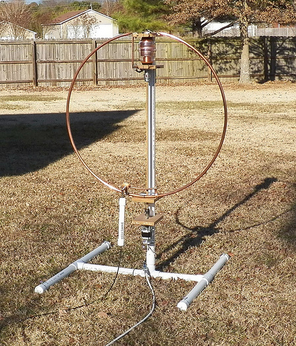
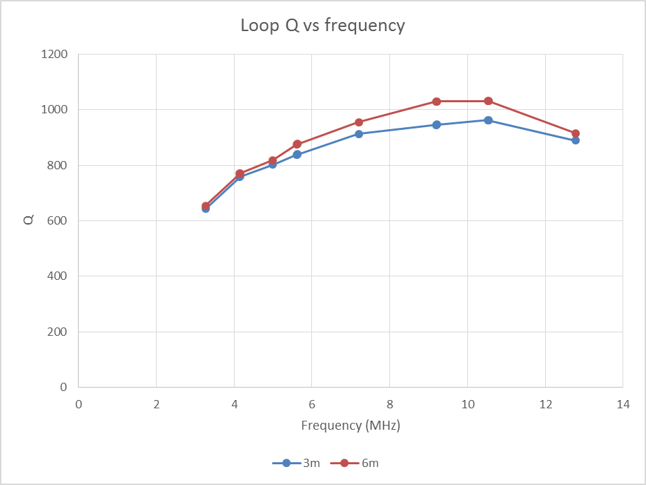
Let me focus on their measurements, the loop was:

  • a 1m diameter circular loop of 6.3mm copper;
  • tuned with a low loss tuning capacitor (ATC chip capacitor);
  • at heights of 3m and 6m above ground;
  • from 3.3 – 12.8MHz.

They did not report the capacitor loss, but gave some likely range from manufacturer’s data.

They used ground parameters G-0.007, εr=17 at 7MHz for their NEC models..

Clip 158

Above is a reconstruction of the measured data from their Fig 3. They measured Rin to their matching transformer and used calculated inductance (relying on the calibrated matching transformer) to calculate Q at each measurement frequency. Continue reading Review of Austin et al paper “Loss mechanisms in the electrically small loop antenna”

Dipole mode component of VK5BR’s 1m square loop for 20m

I mentioned in An NEC-4.2 model of VK5BR’s 1m square loop for 20m that Butler’s ~1m square loop was too large to be considered strictly a Small Transmitting Loop (STL):

Note that the loop is sufficiently large that the current is not uniform around the loop

(Butler 1991) gives a design for a Small Transmitting Loop (STL) for 14MHz and some other bands.

He gives key design data:

Tube Diameter d   0.75 inch
 Circumference S  12.7 feet
 Area A =   10 square feet
 Frequency f =  14.2MHz
 Power P   100 watts
 Radiation Resistance Rr =   0.137 ohm
 Loss Resistance RL =   0.064 ohm
 Efficiency n =  68%
 Inductance L =   3.27 micro-henry
 Q factor =   723
 Inductive reactance XL =   291 ohms
 Bandwidth B =   19.6kHz
 Distributed capacity Cd =   10.4pF
 Capacitor potential Vc =   4587V
 Tuning capacitor Ct =   28pF

The data above appear to ignore some important factors, and estimate some others based on an assumption of uniform current. Continue reading Dipole mode component of VK5BR’s 1m square loop for 20m