Exploiting your antenna analyser #4

Measure MLL using the half ReturnLoss method

Again in the theme of measuring something known, let us determine the matched line loss (or normally quoted attenuation) of our cable at 3.5MHz.

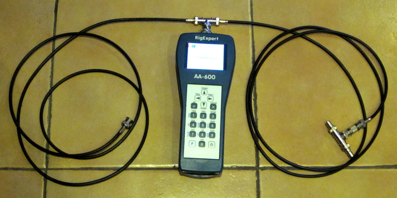
To make the measurement, just connect the two test line sections used in the earlier articles in this series in cascade with a joiner, and one end on the instrument, other end open circuit, and measure ReturnLoss.

Most analyser manuals and lots of helpful articles in journals and handbooks will tell you that MLL=RL/(2*length) where RL is the ReturnLoss of an open circuit or short circuit line section (the only requirement is that the ρ=1 at the line end).

Screenshot - 10_12_2015 , 8_20_14 AM

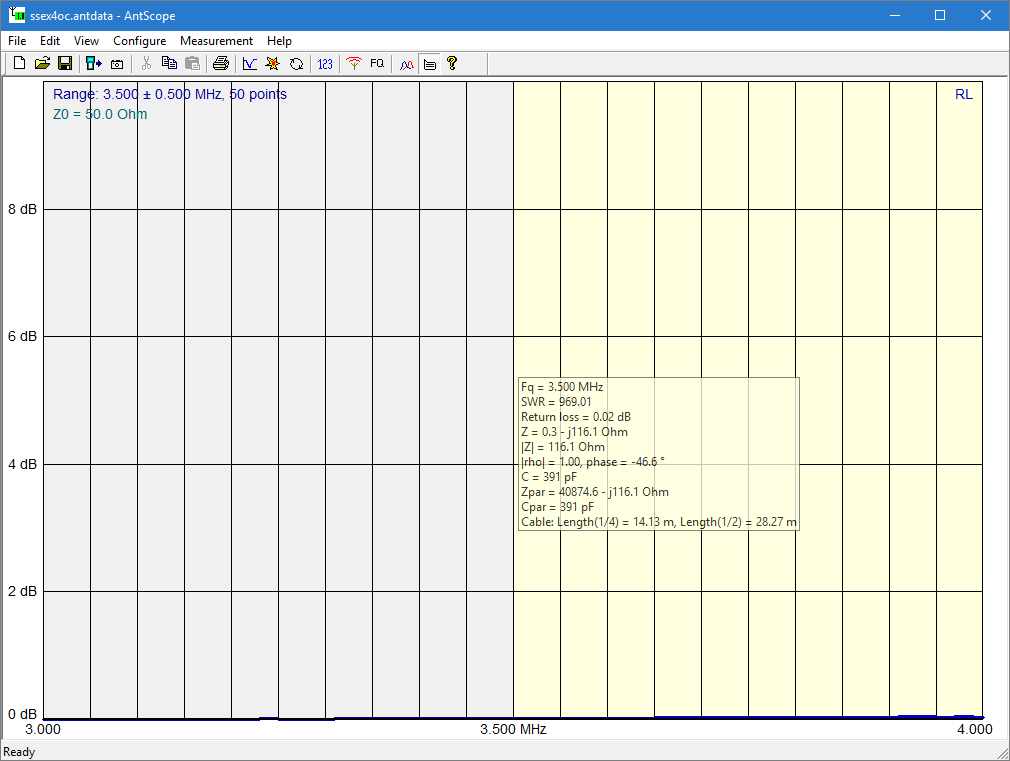
Wow, that is so low, and using the traditional formula:

MLL=0.02/(2*4)=0.0025dB/m.

Of course we are measuring way low in the instrument’s capability and there is some considerable uncertainty… but when we consult a good transmission line loss calculator, we expect around 0.029dB/m… that is 12 times what we measured. Continue reading Exploiting your antenna analyser #4

Exploiting your antenna analyser #3

The sign of reactance

At Exploiting your antenna analyser #2, the matter of determining sign of reactance was mentioned.

If you have an analyser that does not measure the sign of reactance, this information should be important to you.

Screenshot - 9_12_2015 , 8_24_15 AM

Above is a Smith chart plot of  measurements from 15MHz to 25MHz.

One can see that the locus of Zin on the Smith chart forms an arc, and the points on the arc rotate clockwise about the arc centre with increasing frequency. Continue reading Exploiting your antenna analyser #3

Exploiting your antenna analyser #2

Reconciling the single stub tuner results

So having found that the length of the RG58 lines sections are both 1.98m (approximately 2m), let’s try to reconcile measurement and prediction of Zin at 9MHz.

The examples discussed in this series of articles are designed for the test jig as described at Exploiting your antenna analyser #1 with a pair of nominally 2m length RG58 patch leads, a pair of 50Ω loads and some tee pieces and adapters to connect it all up. If you duplicate it, you will experience the same learning opportunities (the examples are structured). If you presume to redesign the experiment, your outcome will probably be different.

Before you read on, take a measurement of Zin at 20MHz and write down the impedance value. Do whatever you do to determine the sign of the reactance. If your instrument displays the sign properly, use it, otherwise use the method in your user manual or whatever wisdom you trust.

Done that? If so, read on… Continue reading Exploiting your antenna analyser #2

Exploiting your antenna analyser #1

I often see posts in online fora by people struggling to make sense of measurements made with their antenna analyser.

This article is about exploitation of a modern antenna analyser beyond its capability as a self excited VSWR meter. The latter is fine, and it is often not only all you need, but the best tool in optimising some antenna systems… but if you want to exploit the other capabilities of the instrument, read on.

Great benefit can be obtained by measuring some known loads, and reconciling the measurement with the known.

A quite simple set of equipment can be used to create a scenario rich with opportunity to prove your understanding of the basics of complex impedance, transmission lines, and measurement. Lets explore a simple example.

AnTestJig01

Above is a test jig. It is two equal lengths of identical coax connected to a tee piece on the analyser. The end of one piece of coax has a tee piece with two nominal 50+j0Ω loads as used on Ethernet 10base2 networks. The analyser is a Rigexpert AA-600. Continue reading Exploiting your antenna analyser #1

Win 10 Threshold 2 issues

I have recently installed the Threshold 2 update to Win 10, and apart from a number of small issues, it seriously broke my grabber environment on a 64 bit machine.

The error messages:

5 [main] lftp 2944 C:\bin\lftp\bin\lftp.exe: *** fatal error in forked process - fork: can't reserve memory for parent stack 0x600000 - 0x800000, (child has 0x400000 - 0x600000), Win32 error 487
1481 [main] lftp 2944 cygwin_exception::open_stackdumpfile: Dumping stack trace to lftp.exe.stackdump
6 [main] lftp 5008 fork: child -1 - forked process 2944 died unexpectedly, retry 0, exit code 0x100, errno 11
...

For that environment, I use an lftp port to Windows (https://nwgat.ninja/lftp-for-windows/), and had installed the 64bit verion which is essentially a cygwin compilation packaged with the necessary DLLs. (This issue probably more widely affects cygwin, or perhaps just the bash shell under cygwin.) Continue reading Win 10 Threshold 2 issues

Expression of VSWR as a simple decimal real number

Voltage Standing Wave Ratio is the ratio of the voltage maximum (antinode) to the adjacent voltage minimum (node) on a transmission line. (This assumes a fully developed standing wave, that the maximum and minimum are not forced by end of line). Continue reading Expression of VSWR as a simple decimal real number

VSWR=1 and X≠0

Another of those threads has broken out on eHam illustrating that lots of hams do not understand the complex nature of impedance and cannot see the consequences of the formula to calculate VSWR from load impedance and transmission line characteristic impedance.

Most methods of measuring VSWR are indirect, and they are based on an assumed Zo which is purely real (ie Xo=0Ω), and we speak loosely of that as the VSWR even though the standing wave that might exist on a practical transmission line is a little different as a consequence of that assumption being a little bit in error. Continue reading VSWR=1 and X≠0

AUT – MobileOne M40-1 40m helical

This article describes an Aerial Under Test (AUT) that features in some of my experiments and write ups and is subject of some current experiments. It is a MobileOne M40-1 helically loaded vertical for 40m installed in the car roof. It is in the style of the popular US antenna, the Hamstick, but this is a little longer and the results are not directly applicable.

I hasten to add that this configuration is not suited to travelling, it is just a rather ideal mounting of a helically loaded whip without the questions that arise from the effects of roof racks, bumper mounts etc.

M40-1

The M40-1 is fitted in the centre of the station wagon roof, the roof is 1.5m above ground and the antenna is 1.5m long including a 200mm unloaded tip (tip of the antenna is highlighted with a pink dot). (The setting is not the test site.) Continue reading AUT – MobileOne M40-1 40m helical

RC PWM – ON/OFF switch

This article describes a remote ON/OFF switch which uses an RC receiver and adapter chip to convert the RC PWM signal into an ON/OFF output. (Suitable RC transmitters are on hand.)

The immediate application is for remote ON/OFF PTT or KEY of a transmitter for field strength testing at various locations.

Background

Remote control hobbies have long used a multi channel digital proportional protocol for control of planes etc. The simplest multi channel receiver has an independent PWM output for each servo.

The PWM signal is a 1000-2000µs pulse with a repetition rate from about 50Hz up to 500Hz or so, the duration of the pulse conveys the information.

Implementation

The converter chip is a ATTiny25 MCU with firmware that monitors the PWM stream and provides ON/OFF and OFF/ON output pins. For the immediate application, the ON/OFF (or non inverted) output drives a 2N7000 FET with ‘open collector’ output suited to the PTT and KEY lines of most modern transceivers.

The firmware ignores PWM signals with duration outside the range 900µs to 2100µs, and switches ON at 1600µs, and OFF at 1400µs to provide some hysteresis. If PWM input is lost for 125ms, the output will fail safe OFF.

rcsw01Above is the schematic. The 2N7000 is good for 60V, can handle up to 100mA without a heat sink, and had a body diode to absorb transients if the load is a relay. Continue reading RC PWM – ON/OFF switch

Proposed 60m amateur band power limit

The WIA announced on 19/11/2015:

The World Radiocommunication Conference (WRC-15) in Geneva has agreed on a secondary allocation of 5351.5-5366.5 kHz for the Amateur Service, with regional power limits of 15 watts to 25 Watts measured in effective isotropic radiated power (EIRP).

This prospect has lots of hams excited, and some wringing their hands over the power limit expressed in the release.

Compliance with this power limit (15W EIRP in this region) may well challenge most modern hams (though EIRP power limits are not new to the Amateur LCD) and perhaps if that is to be the limit, a set of simple compliance guidelines be endorsed by ACMA to assist compliance. Continue reading Proposed 60m amateur band power limit