WSPR (weak signal propagation reporter) is a system for recording on a central database, ‘spots’ of transmitting stations by receiving stations.
It is interesting to examine the contribution by transmitting and receiving stations, for without both, the system cannot work.
I downloaded the archive for December 2015 and did some basic analysis to explore the pattern of use on the 40m band, my main band of interest. Importantly, 40m provides opportunity for local, intermediate and long distance propagation though long distance paths might be restricted to just several hours on most days.

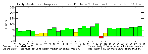
The chart above shows that the T-index was near normal on most days, and 6 days it was quite poor, so propagation conditions during the month will be a little depressed. The effect on 40m is mainly on short ionospheric paths, say 50-500km. Continue reading Evolution of WSPR
Last update: 7th March, 2017, 9:42 AM