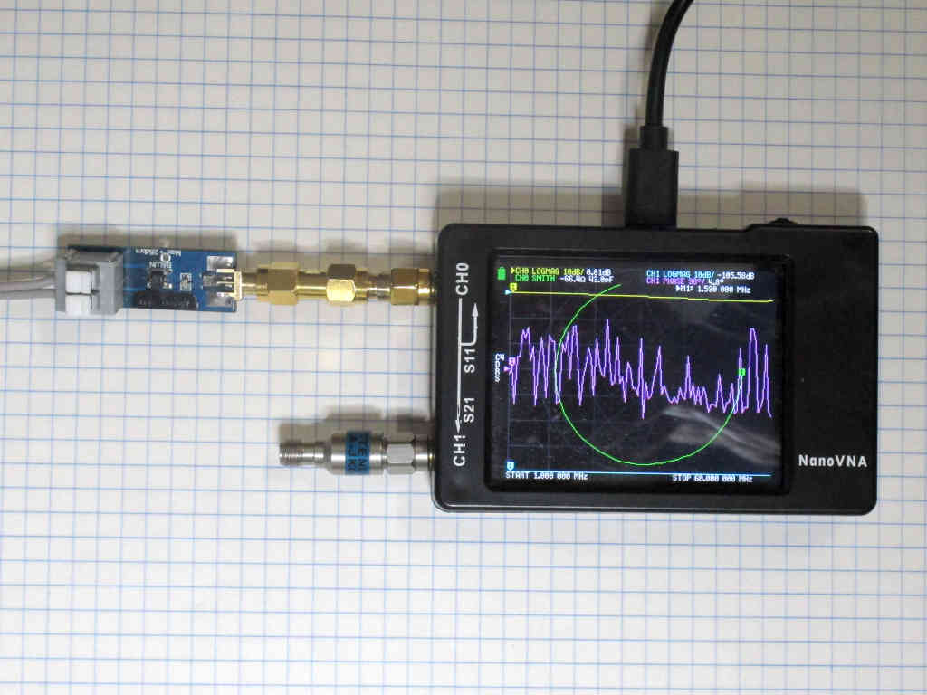
This article series shows how to measure matched line loss (MLL) of a section of two wire line using an analyser or VNA. The examples use the nanoVNA, a low end inexpensive VNA, but the technique is equally applicable to a good vector based antenna analyser of sufficient accuracy (and that can save s1p files).
On testing two wire line loss with an analyser / VNA – part 1
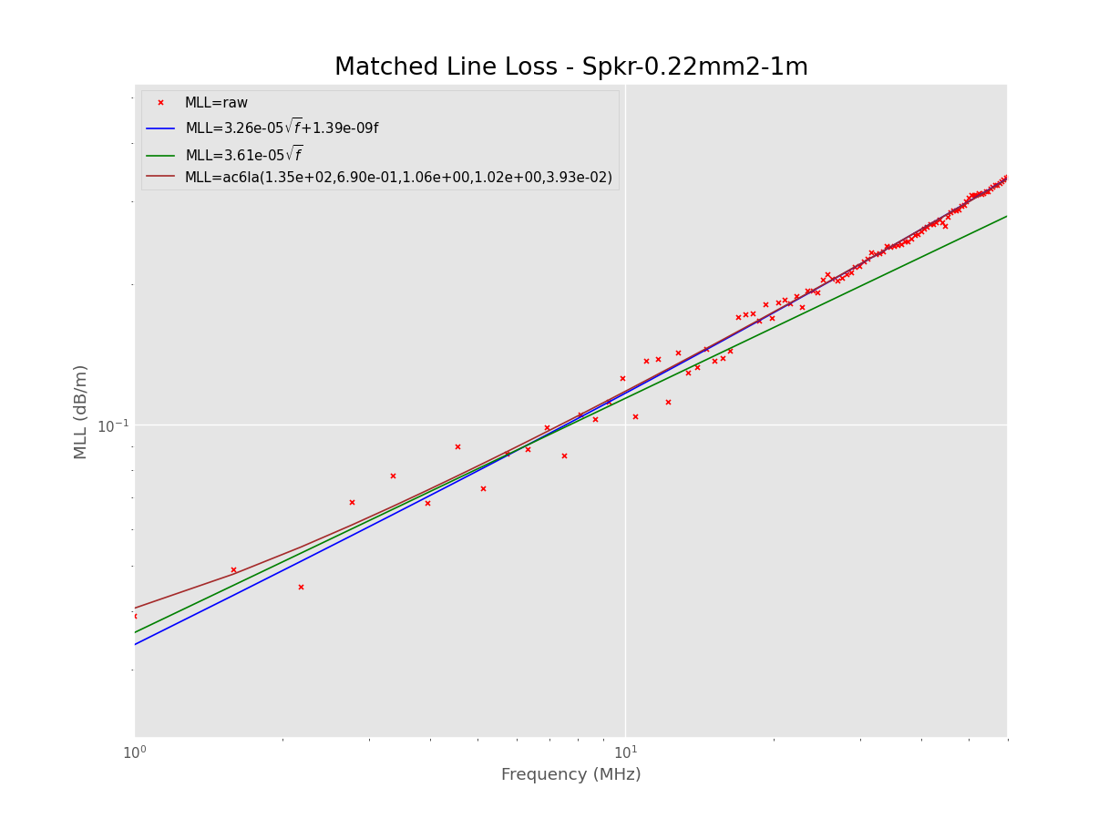
This article series shows a method for estimating matched line loss (MLL) of a section of two wire line based on physical measurements (Duffy 2011).
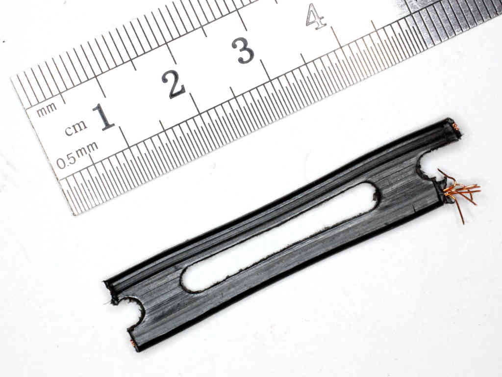
Above is a short piece of the line to be estimated. It is nominal 300Ω windowed TV ribbon. It has copper conductors, 7/0.25, spaced 7.5mm. The dielectric is assumed to be polyethylene… but later measurements suggest is has slightly higher loss than polyethylene. The test section length is 4.07m. Continue reading On testing two wire line loss with an analyser / VNA – part 3