VU3SQM directional wattmeter build – #3

VU3SQM directional wattmeter build – #1 laid out the first steps in design review and build of a directional wattmeter.

The parts have arrived and construction commenced.

Above, the PCB populated with the SM parts and soldered. It was soldered in an IR reflow oven. Continue reading VU3SQM directional wattmeter build – #3

Designing a Gamma Match – confirmation of as-built antennas

Much is written about the virtue of the Gamma Match, and near as much about how they work, and the difficulty in design and implementation.

Designing a Gamma match using a Smith chart showed a design method for a simple Gamma Match using a Smith chart as the design tool.

This article visits the implementation on a pair of antennas that I built 50 years ago, and are still in use today (albeit with some small preventative maintenance once during that interval). The basic antenna is a four element Yagi for 144MHz copied from an ARRL handbook of the time, probably based on NBS 688. It was designed to deliver a split dipole feed point impedance of 50+j0Ω.

I built them using a Gamma Match, partly to get some familiarity, but mostly to implement a Gamma Match that was reliable, weatherproof and lasting… features that are alien to most implementations I had seen at that point.

Both antennas were constructed and the Gamma Match adjusted for VSWR<1.1 using a Bird 43 directional wattmeter. The dimensions of each (including the key gamma dimensions) are the same, not surprising, but a confirmation of repeatability. See Novel Gamma Match Construction for more discussion.

Above is a dimensioned drawing of the construction. Continue reading Designing a Gamma Match – confirmation of as-built antennas

Radcom Feb 2019 “cable balun”

A correspondent asked for an explanation of a novel balun described in Radcom Feb 2019 by K3MT.

Above is a diagram of the so-called “cable balun”.

To evaluate it, I have inserted it into one of the NEC models used for the article Baluns in antenna systems, the model used for Model 3 which I will repeat here for convenience. Continue reading Radcom Feb 2019 “cable balun”

VU3SQM directional wattmeter build – #2

VU3SQM directional wattmeter build – #1 laid out the first steps in design review and build of a directional wattmeter.

This article canvasses the issues of the display.

Intention is a digital based display (though not to exclude an analogue meter or bar graph type displays).

So, the output of the AD8307 needs to be digitised.

Let’s first consider the nature of the AD8307.

It is a log detector, so it provides a ‘DC’ voltage proportional to the log of the input signal, but the ‘DC’ voltage can vary very quickly.

The chart above from the AD8307 datasheet shows that the unfiltered response to a burst of RF has a rise time of well under 1µs. Continue reading VU3SQM directional wattmeter build – #2

KA0KA’s Youtube test of ATU balance

K0KA made a quite polished presentation published as a Youtube video explaining how to measure balance performance of an antenna system and an ATU.

He did not define what he means by balance… but it will become apparent.

Midway through his video, he measures the ‘balance’ of a Palstar AT5K (though possibly modified) by connecting a symmetric load consisting of two 470Ω 2% resistors in series and connecting the junction to the ground terminal on the ATU.

Above, from KA0KA’s video, his test load. The oscilloscope probes can be seen.

The oscilloscope channel gains are carefully adjusted to be equal.

KA0KA shows two oscilloscope measurements.
Continue reading KA0KA’s Youtube test of ATU balance

VU3SQM directional wattmeter build – #1

VU3SQM offers an interesting directional coupler based on a Sontheimer coupler, and using AD8307 power sensing for a nominally HF coupler. I must say that I am not a fan of Sontheimer couplers… but that is what the board uses.

This article lays out a preliminary design review to assist in selection of appropriate toroids, and ordering of the needed parts.

PCB

Above, the top side of a PCB. Continue reading VU3SQM directional wattmeter build – #1

Elecraft CP-1 directional coupler – magnetics review

Elecraft produces a directional coupler that may interest QRP aficionados. It comes with instructions for 20dB and 30dB coupling factors rated at 25 and 250W respectively from 1 to 30MHz.

This article reviews the magnetics design of the -20dB / 25W coupler.

The coupler uses a type of Sontheimer coupler (Sontheimer 1966) and these are commonly poorly designed. The first question is whether the magnetising impedance of T2 which appears in shunt with the load is sufficiently high to not give rise to poor insertion VSWR. Continue reading Elecraft CP-1 directional coupler – magnetics review

The first 21 days of Exetel broadband Internet access

We have had wired broadband service delivered to these premises for almost ten years, supplied by five vendors: Telstra Bigpond, iiNet, Amaysim, Southern Phone and now Exetel.

At The first seven days of Exetel broadband Internet access I discussed the performance failure of the service observed over the first seven days.

Following that, a fault report was submitted to Exetel, and at their request, further observation of speed and ping test latency.

Service levels

I have an expectation that “I want it to deliver most of the rated speed, most of the time during the hours that I want to use it”.

As a result of behaviour of the industry, the ACCC gives some guidance on terms used to advertise a service, and a service expectation.

Essentially they say:

Standard Plus Evening Speed—plans using this label will deliver a minimum speed of 30Mbps during the busy period. This plan would be suitable for a higher usage profile (e.g. streaming an ultra-high definition movie and streaming music on one or more other device during the busy period)

So on that measure, how well did they perform?

Above are the results of file transfer tests conducted automatically, the above are filtered for those in the ACCC’s defined “evening hours” on which they base their service level enforcement. All x symbols in the pink area break the 30Mb/s minimum. Continue reading The first 21 days of Exetel broadband Internet access

A fourth round with the FA-VA5 antenna analyser

I recently acquired a FA-VA5 antenna analyser.

Before trusting measurements made with any instrument, its behaviour should be validated, and this article documents issues discovered in one thread of tests. The developer does not like the term “defects”, he prefers “issues”, a soft denial of “problems”.

So, the test scenario is the VA5 measuring the impedance looking into a 35m length of RG6 coax with an open circuit at the far end. The VA5 has been SOL calibrated with the higher quality loads sold by SDR-kits, and the test is a 3.5MHz. The firmware is the latest, v1.08 (about 3 months old).

The screenshots are taken with a camera, there does not seem to be a method of uploading screenshots to a PC.

Above is a swept Z measurement just above the half wave resonance of the line section. The impedance at the marker is comparable with that measured using an AA-600, so I would accept that it is probably correct. The graph is another matter. Continue reading A fourth round with the FA-VA5 antenna analyser

STC-1000 firmware change

I have an inexpensive (~$10 inc post) digital temperature controller that was observed to have very high RF emissions and was unusable because it was incompatible with radio operations here.

There has been enhanced firmware for a STC-1000 controller based on a PIC chip, but in my experience, most seem to be made with an STM8S003F3 chip. More recently, what appears to be a port of the PIC software to STM8 has been published at https://github.com/Emile666/stc1000_stm8.

The enhanced firmware is directed at home brewing for control of long running fermentation processes etc, incorporating storage for a number of multi-step programs (profiles). It is not really suited to more general applications like a fridge controller as for example it is more difficult for the common operation to set the set point.

I thought it might be entertaining to try it out.

Installation of the firmware was straight forward, I had the necessary programming adapter and software.

Interestingly, after updating the firmware, the device would not start on its original power supply. My suspicion is that the new firmware runs the LED display at higher duty cycle and the power supply could not withstand the load.

Since the power supply had RF emission problems, it was removed and the device converted to 12V DC.

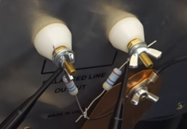
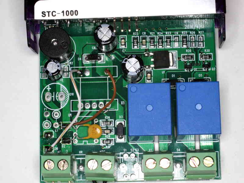
Above, the large components of the switched mode power supply were removed, a Polyswitch protective device installed and input routed to the output terminals of the old 12V output switched mode power supply (white wire is -ve, brown wire is +ve). Continue reading STC-1000 firmware change