MFJ ATU hand effects on capacitor knobs

The problem

Users of some ATUs may have noticed particular sensitivity to hands on the capacitor adjustment knobs. It is a common problem with cheap implementations of the T match as the capacitor rotor is usually at high RF voltage and if that shaft is extended to the adjustment knob, under certain circumstances tuning becomes very sensitive to hands on the knobs.

In some of these implementations, if the users hand touches the metal grub screw in the knob, or the metal panel bushing behind the knob they may get a significant RF burn.

The cause

Let’s use the MFJ-949E as a discussion example. It is a T match, and the metal capacitor shafts in the knobs and panel bushings carry RF voltages.

So why is this only sometimes a problem?

The RF voltage across the coil, and impressed on the capacitor shafts can be extremely high when using loads with small resistance and large negative reactance, more so on the lower bands. Continue reading MFJ ATU hand effects on capacitor knobs

WIA 4:1 current balun – further measurements

4-101a

I mentioned in my article WIA 4:1 current balun that the use of a single toroidal core in the above graphic compromises the balun. This article presents some simple measurements and analysis that question whether the balun works as so many users think.

The popularity of the balun derives from the work of VK2DQ and is often known as the VK2DQ 4:1 current balun (though probably not his invention).

Analysis at the limits

Often, analysis of a network as frequency approaches zero or infinity can simplify the analysis whilst allowing a reasonable test of the sanity of the design.

Above is a conventional transformer schematic of the WIA 4:1 current balun on a perfectly symmetric (balanced) load. At frequencies where the electrical length of each winding is very short, we can assume negligible phase delay along or between windings, simplifying analysis greatly. Continue reading WIA 4:1 current balun – further measurements

4:1 current balun – identifying bad ones

Correspondents have informed me that the balun dealt with in article 4:1 current balun – review and fix and variants are very common. This article gives a checklist of common issues and some basic measurements using an antenna analyser that should reveal some issues without breaking into a sealed assembly.

Introduction

Baluns are commonly employed to obtain nearly balanced feed line currents (ie negligible common mode current) in two wire lines or negligible common mode current on coaxial feed lines. This article discusses baluns for that application.

A very common 4:1 current balun is Guanella’s 4:1 current balun, but there are others including pretenders.

Three common 4:1 current baluns

Guanella 4:1 current balun

(Guanella 1944) described a 4:1 current balun in his 1944 article, he did not show the winding pairs coupled by a magnetic core as shown above.

Guanella421

Above is Guanella’s circuit, and he does not show coupling between the two winding pairs.

Properly implemented, this device is known to work very well.

Sevick’s single core 4:1 current balun

Let us look at Sevick’s device because it underlies so many failures.

If you look at it very carefully, you will see that the two output wires emerge from opposite sides of the core, the left hand wire exiting under the core was wound from front to back of the core and the right hand wire exiting on top of the core was wound from back to front of the core. Continue reading 4:1 current balun – identifying bad ones

4:1 current balun – review and fix

This article reports tests on two 4:1 current balun configurations – a collaboration between Bruce, VK4MQ, and myself.

Purported current balun on a single magnetic core

Above is an attempt at a 4:1 current balun on a single core. Note that this is NOT wired in the insane series opposed connection of the WIA 4:1 current balun. Note also that this is NOT a Guanella 4:1 current balun (see below).

Lets measure the Insertion VSWR by placing a good 200+j0Ω load on the output terminals and measuring input VSWR over the range 1-30MHz. This load is what we will call an Isolated Load meaning it has only two terminals, and the current that flows into one terminal must flow out of the other terminal… in other words, the current MUST be balanced (ie equal magnitude but opposite phase currents in the two terminals)… we will come back to the Isolated Load later.

Above, measured InsertionVSWR. It is not too good, but not very bad either. Broadly the balun gives an almost reasonable 4:1 impedance transformation from load to input. Continue reading 4:1 current balun – review and fix

Annual inspection of antenna reveals balun box issue

During annual inspection of my HF antenna system, I removed the lid from the common mode choke.

AtuBalun202

The choke is housed in a (German) Hensel PS electrical terminal box. Hairline cracks were observed radiating out from one of the terminal screws, and adjacent to both screws in the lid. The lid is obviously not strong enough to be secured by two screws in the way done. Continue reading Annual inspection of antenna reveals balun box issue

Radcom Feb 2019 “cable balun” – comment on Radcom “The last word” letter

At Radcom Feb 2019 “cable balun” and
Radcom Feb 2019 “cable balun” – a deeper look I wrote about a novel balun by K3MT.


Fig 1

Above is a diagram of the so-called “cable balun”.

My evaluation essentially showed that it was not effective in an example practical scenario where one might want to use a balun, and that of itself, it was not likely to significantly reduce common mode current in most scenarios.

Radcom Mar 2020 published  a letter in “The last word” from the author defending the device citing a NEC model of one scenario, curiously though without explanation, a different topology to the diagram above from the original article. Note also that it is a structure in free space with no discussion of how that is relevant to real world antennas near ground. Continue reading Radcom Feb 2019 “cable balun” – comment on Radcom “The last word” letter

nanoVNA-H – a summary of the experience so far

The NanoVNA is a new low cost community developed VNA with assembled units coming out of China for <$50.

I purchased what appears to be a ‘genuine’ nanoVNA-H and it has firmware NanoVNA-H_20191018.dfu installed. During checkout of the delivered device, an issue became evident, an issue worth describing in its own article.

Nevertheless, one online expert assured me it is a fake because genuine ones use green solder mask. Continue reading nanoVNA-H – a summary of the experience so far

nanoVNA-H – sweep of a coax line section with OC termination

This article discusses the use of the (modified) nanoVNA-H raw accuracy and the implications for calibrated measurements.

Introduction

VNAs achieve much of their accuracy by applying a set of error corrections to a measurement data set.

The error corrections are obtained by making ‘raw’ measurements of a set of known parts, most commonly a short circuit, open circuit and load resistor (the OSL parts). The correction data may assume each of these parts is ideal, or it may provide for inclusion of a more sophisticated model of their imperfection. This process is known as calibration of the instrument and test fixture. nanovna-Q appears to have some fixed departure compensation to suit the SMA cal parts, less suited to other test fixtures.

So, when you make a measurement at some frequency, the correction data for THAT frequency is retrieved and used to correct the measurement.

What if there is not correction data for THAT frequency? There are two approaches:

  • a calibration run is required for exactly the same frequency range and steps (linear, logarithmic, size) as the intended measurement; and
  • existing calibration data is interpolated to the frequency of interest.

The interpolation method is convenient, but adds uncertainty (error) to the measurement. Some commercial VNAs will NOT interpolate.

The nanoVNA will interpolate, and with interpolation comes increased uncertainty.

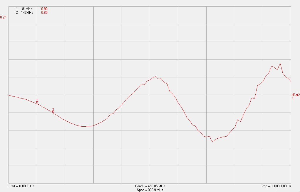
An uncorrected sweep of a reasonably known DUT is revealing of the instrument inherent error.

The DUT is a 12m length of LMR400.

Expected behavior

Let’s first estimate how it should behave.

The VNA contains a directional coupler nominally designed / calibrated for Zo=50+j0Ω, and in use, VNAs are invariably used to display measurements in terms of some purely real impedance, commonly 50Ω.

Though the DUT characteristic impedance (Zo) is nominally 50Ω, it is not EXACTLY 50+j0Ω and so there are departures in the displayed values wrt 50Ω from what might happen in terms of the actual Zo.

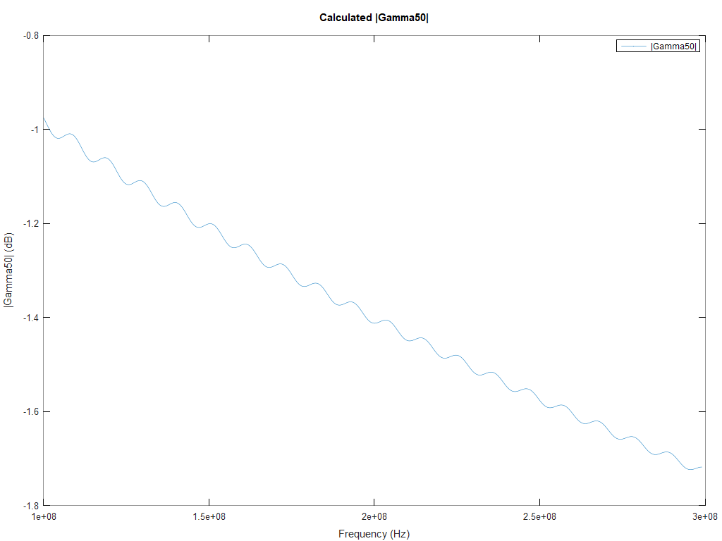
We can calculate the magnitude of Gamma for our 12m OC section of LMR400 over a range of frequencies.

|Gamma| vs frequency is a smooth curve as a result of line attenuation increasing with frequency. As a result in the small departure in Zo, |Gamma| wrt 50Ω has a superimposed small decaying oscillation. Continue reading nanoVNA-H – sweep of a coax line section with OC termination

nanoVNA-H – T-Check test

Rhode & Schwarz describe a test for accuracy of a VNA at T-Check Accuracy Test for Vector Network Analyzers utilizing a Tee-junction.

A nanoVNA-H PCB v3.3 (modified to fix decoupling problem on mixers) was calibrated from 0.1-900MHz using the supplied parts.

A T piece with extra 50Ω termination was inserted between the supplied original cables and s11 and s21 captured. The assembly was turned around and measured again to capture s22 and s12 (though recorded as s11 and s21). The two files were merged to obtain a full two port bothways .s2p file.

The T-Check value was calculated and is plotted here in VNWA.

Above, the T-Check results are not stunning at all, the ideal result is 1.0 at all frequencies. Rhode and Schwarz recommend that more than 15% error is unacceptable… of course that is in a commercial grade VNA.