Exploiting your antenna analyser #28

Resolving the sign of reactance – a method

Many analysers do not measure the sign of reactance, and display the magnitude of reactance, and likewise for magnitude of phase and magnitude of impedance… though they are often incorrectly and misleadingly labelled otherwise.

The article The sign of reactance explains the problem and dismisses common recipes for resolving the sign of reactance as not general and not reliable.

This article gives an example of one method that may be useful for resolving the sign of reactance.

My correspondent has measured VSWR=1.68 and |Z|=66 and needs to know R and X. From those values we can calculate R=60.3 and |X|=26.9.

Method

The method involves adding a short series section of known line, short enough to provide a measurement difference in R, and that R would be different for the case of =ve and -ve X, all of these measured at the same frequency. Continue reading Exploiting your antenna analyser #28

Ground plane ham myth – inclined radials

From time to time one sees ‘traditional wisdom’ that inclining the radials of a VHF ground plane to raise its feed point resistance degrades it performance significantly.

I have constructed NEC-4.2 models of a 52MHz ground plane with four 45° inclined radials at 10m height above ‘average ground’ (σ=0.005, εr=13) on and connected to a conductive support pole which is bonded to ground at the lower end, and one with horizontal radials.

Comparing the patterns at low angles shows there is not much in it, but below 32° elevation which tends to be of greater interest at VHF, the winner is actually the inclined radials though the difference is less than 1 dB. Continue reading Ground plane ham myth – inclined radials

Matching a 5/8λ ground plane

The 5/8λ ground plane is regarded by hams widely as a superb antenna for DX, and since the main reason for modern ham radio is DX, it is an antenna of interest.

The idea behind the 5/8λ ground plane popularity is that claim that it has higher gain at low angles than a simple 1/4λ ground plane.

The 5/8λ ground plane is not resonant, and the feed point impedance is hardly suited to direct coax feed.

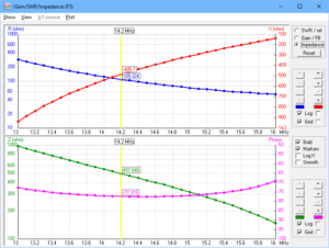
The chart above is for a 5/8λ ground plane elevated to 5m height above average ground (σ=0.005, εr=13). The feed point impedance in this case at 5/8λ radiator height (14.2MHz) is about 110-j485Ω. Continue reading Matching a 5/8λ ground plane

Common mode impedance of W2DU baluns

Walt Maxwell (W2DU) described a simple common mode choke or 1:1 current balun using ferrite sleeves slipped over a coaxial cable.

Fig 1:

Maxwell gives the choking impedance of two of his recommended chokes in Fig 21-3 from (Maxwell 2001). He does not give any detail of how he arrived at the curves, and in correspondence declined to give any detail.

This article focusses on a linear design for HF using 50 x FB-73-2401 (2673002402) ferrite sleeves.

The question that arises is how do you measure the impedance of a component that is 250+mm between terminals. Continue reading Common mode impedance of W2DU baluns

STL propaganda indeed: QW vertical – dipole – STL model pattern comparison

STL propaganda indeed: dipole – STL pattern comparison compared the patterns of a Inverted V dipole and STL, both configurations typical of SOTA deployments.

Seeing some pretty wild extrapolations to a vertical quarter wave with elevated radials, again typical of SOTA deployment, this article presents a comparison of all three using NEC-4.2 models.

See STL propaganda indeed and STL propaganda indeed: dipole – STL pattern comparison for details of the models for the STL and dipole.

The QW vertical is modelled using 2mm dia copper wire for vertical and radials, the radials are elevated 0.5m over ‘average ground’ (σ=0.005, εr=13).

Bear in mind that these are models that are based on some assumptions like ground parameters for example, and results may be different for other scenarios. Likewise, the results at 20m cannot simply be extrapolated to other bands, and practical modes of propagation utilised vary from band to band.

Key differences

Polarisation

Polarisation is a significant difference. Vertical ground waves are attenuated more slowly than horizontal waves, though ground wave propagation is not so commonly exploited on 20m due to its very short range. Because vertical ground waves are attenuated more slowly, a vertical polarised receiving antenna is likely to capture more ‘local’ noise that a horizontal one, but in SOTA context, local noise is not such an issue on mountain tops.

The QW vertical is vertical polarisation.

The STL is vertical polarisation.

The Inverted V dipole is horizontally polarised broadside to the dipole, and tends to vertical polarisation off the ends.

Radiation pattern

Radiation pattern is a 3 dimensional characteristic, often selectively plotted in two dimensions in the most favorable plane… which is fair enough but the reader needs to keep in mind the bigger three dimensional characteristic as it applies to their own application.

The radiation patterns of the antennas are quite different, the vertical is omnidirectional in azimuth whereas the others are not. So, it is challenging to produce a single general figure of merit comparing all antennas.

Above is a comparison of gain in the plane of maximum gain of the STL and dipole.  Continue reading STL propaganda indeed: QW vertical – dipole – STL model pattern comparison

A check load for antenna analysers with UHF series socket

Hams embrace the UHF series connectors like no one else, including for its use on test equipment where its performance is lacking.

This is the likely reason why it is so hard to find low VSWR 50Ω terminations with UHF series plug. It is rare to find something with VSWR quoted in specifications, and nigh on impossible to find one at a reasonably low price.

On the other hand, SMA terminations start at about $2 each (posted), and it is not too hard to find ones specified with VSWR<1.2 to several GHz.

Above is a low cost, low quality solution. It is a SMA termination selected from a bunch using a high accuracy DMM (selected, R is 49.86Ω) and a SMA(F)-UHF(M) adapter, total cost $7 (posted) (but you might be advised to buy 5 loads to select the best one). Despite the specification, they are probably only good to 100MHz, and can be unreliable. Continue reading A check load for antenna analysers with UHF series socket

STL propaganda indeed: dipole – STL pattern comparison

At STL propaganda indeed a realistic model was developed of the Chameleon P-Loop2 on 20m, similar to that used in the experiment Comparing the performance of an inverted vee dipole with a small transmitting loop on 20m.

This article presents NEC-4.2 derived radiation patterns for both the loop and Inverted V Dipole used for the experiment using data published in the experiment writeup.

The effect of radiation pattern

The original experiment cited at the start compared WSPR signals received by a number of stations at moderate distance, and a key parameter becomes not so much the maximum gain of the two antennas compared but the gain at the relevant path elevations and the higher dipole will tend to have relatively better gain at lower elevation than the lower STL, so that further disadvantages the STL in the test scenario. This factor would be additional to the relative maximum gain of both antennas.

That is not to suggest that the test somehow set out to disadvantage the STL, both antennas were quite typical of SOTA deployments and the relative performance over moderate distance paths is highly relevant to that application.

Patterns from the models

The following patterns are from an NEC model that tries to capture realistic values for significant loss elements that affect the gain of each of the antennas.

The major lobe axis is shown above, and the difference in the patterns varies a little with elevation. at 45° elevation the difference is 6.11–7.72=13.8dB. It should be no surprise to an open mind that  Richard concluded there as an advantage of 12.77dB to the dipole his experiment.  Continue reading STL propaganda indeed: dipole – STL pattern comparison

STL propaganda indeed

Recent postings to List your favorite SOTA antenna on QRZ.com referred to an experiment Comparing the performance of an inverted vee dipole with a small transmitting loop on 20m as propaganda.

The experiment above states The manufacturer of the loop gives a calculated efficiency of 39.754% at 14174 kHz. This is very similar to that claimed by Chameleon of their P-Loop2, so it will be used as a study example.

Experimental method

Taking the Chameleon P-Loop2 on 20m as the study example,

  1. build a model in the AA5TB spreadsheet;
  2. build an NEC-4.2 model in free space and reconcile it with AA5TB;
  3. build an NEC-4.2 model in proximity of ground compare it with AA5TB;
  4. build an NEC-4.2 model in proximity of ground and add realistic estimates for conductor and capacitor loss and compare it with AA5TB;
  5. compare the NEC-4.2 model in proximity of ground with realistic losses to Chameleons published VSWR curve.

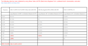
Chameleon gives the following table on their website.

Step1: build AA5TB model

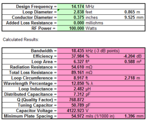
An extract from the AA5TB model using Chameleon’s stated dimensions. The efficiency figure reconciles exactly.  Continue reading STL propaganda indeed

Extrapolating VSWR of a simple series resonant antenna

An online expert helped recently helped his Small Transmitting Loop (STL) disciples with:

Also remember that the bandwidth given by the calculators is the half power point. That’s equivalent to an SWR of about 4.3 at the ends.

Whats that?

Most STL, and lots of other resonant antenna systems exhibit a classic VSWR curve being that of a approximatly constant resistance in series with an ideal capacitor and inductor.

Clip 222

Above is that classic VSWR curve.  Continue reading Extrapolating VSWR of a simple series resonant antenna