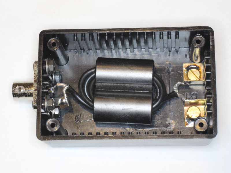
ATU efficiency

Much is written about ATU efficiency, about the need for them or not, and often in subjective terms like “lossy ATU”, and most of it lacking quantitative detail.

The little quantitative detail is almost entirely for purely resistive loads… as if that is typical of real life conditions.

The most common configuration used today is the ‘high pass T match’, but a range of other configurations are seen as being superior… though usually without quantitative evidence.

MFJ claims

More Hams use MFJ-949s than any other antenna tuner in the world! Why? Because the worlds leading antenna tuner has earned a worldwide reputation for being able to match just about anything.

… so let’s make some measurements with a reactive load on a MFJ-949E. Capacitive loads tend to be very common for antenna systems at lower HF, so let’s choose a load of 50Ω with a 100pF silver mica cap in series at 3.6MHz. The reactance of the cap is -442Ω, so the load is 50-j442Ω, and the 50Ω part is a RF power meter (RFPM1).

The test setup then is:

  • a standard signal generator (SSG) on 3.6MHz with 20dB precision attenuator so that we are confident that Zs=50Ω (important to the adjustment of the ATU for maximum power as indication of 50Ω match);
  • MFJ-949E;
  • 100pF silver mica capacitor (low loss);
  • RFPM1

The SSG was adjusted for -10dBm out directly into the RFPM1, then the ATU+cap inserted and ATU adjusted for maximum power indication. Power indicated was 1.4dB lower, so InsertionLoss and TransmissionLoss are both 1.4dB.

Screenshot - 26_02_16 , 19_13_52

Above is a simulation of the T network in RFSim99, component values are adjusted for a match and inductor Q is calibrated to the measured loss of 1.4dB. Continue reading ATU efficiency

Low power Guanella 1:1 tuner balun using a pair of Jaycar LF1260 suppression sleeves

The article describes a current balun intended for use with an ATU at modest power levels. It is lightweight and well suited to portable operations, and can be made with materials readily available in Australia (LF1260 cores are a little over $1 each in packs of six.) Continue reading Low power Guanella 1:1 tuner balun using a pair of Jaycar LF1260 suppression sleeves

Low Insertion VSWR HF Guanella 1:1 balun for instrumentation

The article describes a current balun intended for measurement use with low power instrumentation. It is lightweight and can be made with materials readily available in Australia (LF1260 cores are a little over $1 each in packs of six). The target application is for a 600mm square small loop for field strength measurement below 15MHz.

Design

The design is an implementation of (Duffy 2007) which used RG174 coax for the choke to give low Insertion VSWR.

The balun is intended for low power measurements and will withstand dissipation of a few watts.

The LF1260 cores are made from a medium µ ferrite and have an ID of 7.8mm.

Screenshot - 12_01_2015 , 20_08_34

Above, the cores will accommodate four round conductors of diameter 3.2mm, so they will comfortable accommodate the four passes of RG174 (2.5mm dia). (For the mathematically minded, the minimum enclosing circle diameter for four equal circles is 1+√2 times the diameter of the smaller circles.)

Implementation

LF1260Balun101Above, the balun cores  are housed in a small Jiffy box with a BNC-F flange mount connector at one end and a pair of M4 screw terminals at the other. Small brass tabs were made as non-rotating terminal tags and the M4 brass screws soldered to them. The cores are attached to each other with a piece of double-sided foam tape to prevent them shattering, and two pieces of the same used to secure the cores to the box. A packing between the cores and lid helps to hold them in place.

As discussed at Baluns – show me the numbers, implementation details without quantitative models or measurement are of little value. Continue reading Low Insertion VSWR HF Guanella 1:1 balun for instrumentation

Voltage and current on a transmission line with standing waves

Folk often ask how to calculate the maximum voltage on an antenna feed line with standing waves, often to get a feel for the necessary voltage withstand of baluns, feed line, switches and relays, and ATUs.

Feeding at a current maximum outlines the method described in detail at (Duffy 2011), but the approach is more complex than a lot of hams want.

A simpler method is to treat the transmission line as lossless, and to simply find the worst case voltage and current that can occur… and design for that, or perhaps do the more detailed analysis depending on the outcome.

A new calculator, Calculate Vmax, Vmin, Imax, Imin for lossless line from Zload (or Yload) and Zo, does just that.

Screenshot - 29_01_16 , 19_45_17

Above is the built-in example of a G5RV with tuned feeder on 80m with feed point impedance derived from a modelling package. The voltage and currents calculated are those for a long lossless feed line.
Continue reading Voltage and current on a transmission line with standing waves

Is maximum power transfer and conjugate matching simultaneously possible

A reader has asked the question in a transmission line context after reading Walter Maxwell’s teachings on system wide conjugate matching.

In the real world, transmission lines have loss and almost always, the nature of that loss will mean that Zo is not purely real.

The answer to the question depends on whether or not there are standing waves on the transmission line.

Nothing in this article is to imply that a transmitter is well represented by a Thevenin equivalent source. Continue reading Is maximum power transfer and conjugate matching simultaneously possible

Walter Maxwell’s teachings on system wide conjugate matching

Walt Maxwell (W2DU) made much of conjugate matching in antenna systems, he wrote of his volume in the preface to (Maxwell 2001 24.5):

It explains in great detail how the antenna tuner at the input terminals of the feed line provides a conjugate match at the antenna terminals, and tunes a non-resonant antenna to resonance while also providing an impedance match for the output of the transceiver.

Walt Maxwell made much of conjugate matching, and wrote often of it as though at some optimal adjustment of an ATU there was a system wide state of conjugate match conferred, that at each and every point in an antenna system the impedance looking towards the source was the conjugate of the impedance looking towards the load.

This is popularly held to be some nirvana, a heavenly state where transmitters are “happy” and all is good. Happiness of transmitters is often given in online discussion by hams as the raison d’être for ATUs . Continue reading Walter Maxwell’s teachings on system wide conjugate matching

Transmission line loss under mismatch explanations – the missing TWLLC model

At Transmission line loss under mismatch explanations I wrote that there is a lot of woolly thinking amongst hams about transmission line loss under mismatch and worked a simple example that could be done ‘by hand’ to show that formulas that some authors have produced as implementations of their explanations don’t stack up.

I also gave a solution to the Zo*3 scenario using TWLLC, but not the Zo/3 scenario which a few eagle hounds have pounced on as evidence that the solution would not support the article.

Not at all, the Zo/3 TWLLC solution was not given so as to keep the article short and within the attention span of modern hams though it was eventually a quite long article, and for that reason I will address it separately, here. Continue reading Transmission line loss under mismatch explanations – the missing TWLLC model

Transmission line loss under mismatch explanations

There is a lot of woolly thinking amongst hams about transmission line loss under mismatch, perhaps exemplified by Walt Maxwell (Maxwell 2001):

The power lost in a given line is least when the line is terminated in a resistance equal to its characteristic impedance, and as stated previously, that is called the matched-line loss. There is however an additional loss that increases with an increase in the SWR.

This article probes the folk lore with an example scenario designed to expose the failure of such thinking. Continue reading Transmission line loss under mismatch explanations

Differential flux leakage in a Guanella 1:1 balun – an experiment

The article reports a simple experiment on the balun described at Low power Guanella 1:1 tuner balun using a pair of Jaycar LF1260 suppression sleeves to assess the loss with near zero common mode current.

This test would not subject dielectrics to high electric field strength.

LF1260x2-01

The balun above had the two wires at one end connected together, and a current of 1.41A at 7MHz passed between the terminals of the device at the other end.

The device so configured looks like a s/c transmission line stub and we would expect that the input impedance would be a very small resistance and small inductive reactance. Continue reading Differential flux leakage in a Guanella 1:1 balun – an experiment

Balanced ATUs and common mode current

This Feb 2012 article has been copied by request from my VK1OD.net web site which is no longer online. The article may contain links to articles on that site and which are no longer available.

Many designs have a ‘balanced output’ or an option of a ‘balanced output’, but what does that mean, and are they effective in minimising common mode current in an antenna feed line?

ATUs achieve ‘balanced output’ in one of several ways, the common ones are:

  • a grounded impedance transformation network followed by an internal voltage balun;
  • a grounded impedance transformation network followed by an internal current balun;
  • a current balun followed by a symmetric impedance transformation network that may or may not be directly grounded at its centre;
  • a link coupled ATU where the output circuit is symmetric and may or may not be directly grounded at its centre.

Much has been written about the merits of one approach or another, mostly qualitative and often subjective, but there is little in the way of quantitative analysis of the impedance that the ATU offers to common mode current. Continue reading Balanced ATUs and common mode current