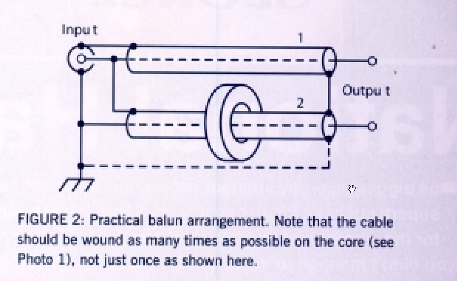
Kenwood R-5000 thermals

I have a Kenwood R-5000 that is now 30+years old and warrants a check of its health.

R-5000s are infamous for VCO problems, the early production used ‘yella glue’ to stabilise the VCO components and that decomposed into corrosive components that damage the electronic parts. Repair is not usually economically rational.

This is one of the later model R-5000s that used the hard white adhesive which has remained stable.

The R-5000 is built on phenolic PCB and operates at relatively high temperature for a simple receiver, reflecting the power consumption of synthesisers of the 1980s.


Above, the case temperature is up to 20° above ambient over the power transformer (upper right of pic).  Continue reading Kenwood R-5000 thermals

Estimating the voltage impressed on the tuning capacitor of a small transmitting loop

The ‘net abounds with calculators for design of small transmitting loops (STL), and most estimate the voltage impressed on the tuning capacitor. Most of these calculators give an incorrect estimate.

This article describes a measurement based approach to estimating the capacitor voltage for a STL.
Continue reading Estimating the voltage impressed on the tuning capacitor of a small transmitting loop

A QRP small transmitting loop evaluation

The ‘net abounds with articles describing easy to build low cost small transmitting loops (STL).

This article describes measurement of a STL for 4MHz using RG213 coaxial cable for the main loop and its tuning capacitance, and a smaller plain wire loop for transformation to 50Ω. Continue reading A QRP small transmitting loop evaluation

Precise RF small transmitting loop

Precise RF have announced two small transmitting loops for amateur radio, this article looks at the Precise High Gain Loop.

Description

The antenna is described at (Precise RF 2017).

Above is an extract from a table in the brochure comparing the subject antenna to some others.

On a quick scan, the standout figure is gain of 2.8dBd presumably at a loop height of 4.57m (15′), and without qualification of frequency. Elsewhere in the brochure there is a note that 80m requires an optional ‘resonator’… presumably a larger loop.

Lets review the meaning of dBd

The ITU Radio Regulations (ITU 2012) gives us a definition for antenna gain that captures the meaning of dBd that is accepted by most regulators and industry world wide.  Continue reading Precise RF small transmitting loop

The sign of reactance – SM6WHY’s take

As the popularity of low cost, low end antenna analysers increases, client software appears to enhance the capability of the analyser.

The SARC-100 is one of these low end analysers, it and its many close derivatives are marketed under various model names.

The sign of reactance discusses a major weakness of these and many other low end instruments in that they do not ‘measure’ the sign of reactance, displaying the magnitude of reactance and leaving it to the user to solve the sign problem.

SM6WHY is one of the many who have produced software for the SARC-100 that purports to solve the sign of reactance problem. He gives this graphic on his website to demonstrate the capability of his software used with a SARC-100 (which does not sense the sign of reactance).

Above is part of the graphic he offers. Though the image is poor quality, the VSWR plot appears smooth and quite typical of that which might be obtained by measuring an antenna system near its VSWR minimum.

However the accompanying Smith chart plot which has points plotted with both negative and positive reactance is inconsistent with the VSWR plot and appears flawed.  Continue reading The sign of reactance – SM6WHY’s take

Shunt matching a loaded HF whip – discussion

Shunt matching a loaded HF whip with just a VSWR meter gave a direct answer and supporting explanation to an online poster’s question about optimising an 80m loaded mobile vertical with shunt matching, specifically the inductor needed and an adjustment procedure.

The original poster clearly had the impression that this improvement of the original VSWR=1.3 would make a large difference.

The only other option for me is to remove the shunt and set my swr back to 1.3:1 and not be able to communicate.

Continue reading Shunt matching a loaded HF whip – discussion

Power in a mismatched transmission line

This is a republication of an article posted on VK1OD.net Jun 2012.

This article presents a derivation of the power at a point in a transmission line in terms of ρ (the magnitude of the complex reflection coefficient Γ) and Forward Power and Reflected Power as might be indicated by a Directional Wattmeter. Mismatch Loss is also explained. Continue reading Power in a mismatched transmission line

Shunt matching a loaded HF whip with just a VSWR meter

A question was asked on one of the popular online forums:

How to get the most out of an 80 mobile antenna?…I am using a hustler antenna and I had the swr down to 1.3:1. I started researching how to make the antenna better and it seems that maybe an inductive shunt at the base of the antenna to ground would help. I don’t have the equipment to analyze the antenna and the shunt reactance. I made a 9 turn coil 1″ in diameter and 1″ long using n0. 12 awg thnn wire. I installed the coil at the base of the antenna and now the best swr that I can get is 1.8:1. So is there a way that I can set up the coil and antenna using only an swr meter?…

After 50 responses, none of the online experts have offered a direct answer or explanation.

Direct answer

The coil inductance is too low, try a solenoid of 13 turns, 40mm diameter and 40mm length.

Explanation

An antenna of this type at minimum VSWR will have a feed point impedance of near zero reactance and resistance equal to 50 divided by the measured VSWR, so in this case 39Ω. Continue reading Shunt matching a loaded HF whip with just a VSWR meter

G4JNT’s observation of bandwidth effects on WSPR SNR

G4JNT reported some measurements of WSPR reported SNR vs input signal at (Talbot 2010).

His experiment connected a WSPR modulated RF source directly to an SDR receiver, and he recorded WSPR’s receive SNR reports vs input attenuation and configured SDR receiver bandwidth. The direct connection means the test is not subject to normal radio path effects like fading.

The table above is derived from Talbot’s, his information about the RF source (-30dBm) and attenuator settings are converted to receiver input power (dBm).

Above is the same data charted. A linear line fit to the 300Hz data is also included, it is a very good fit. The issue that Talbot raised is that the reported SNR is quite dependent on receiver bandwidth. Continue reading G4JNT’s observation of bandwidth effects on WSPR SNR