This article is a review of an inexpensive QRP ATU kit sold widely on eBay and possibly other online stores.
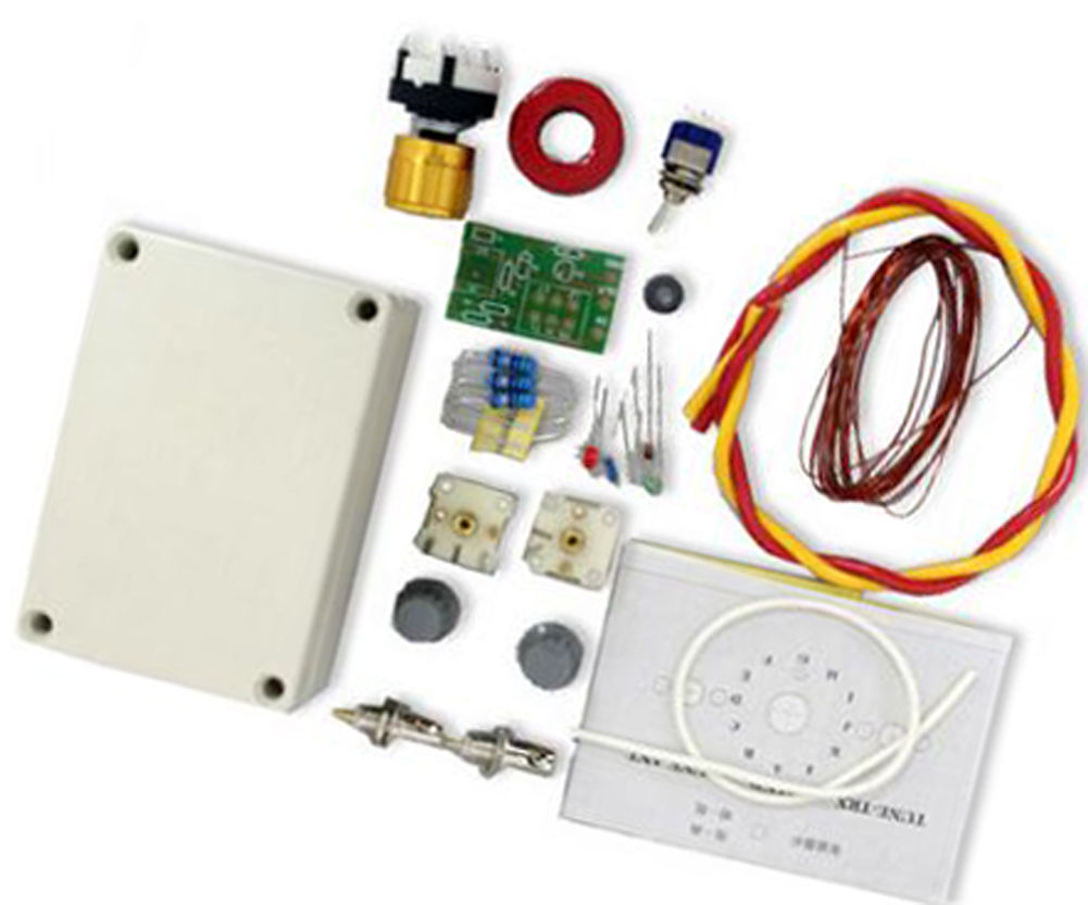
Above is the seller’s pic of the kit. Continue reading Review of inexpensive QRP ATU kit from eBay
This article is a review of an inexpensive QRP ATU kit sold widely on eBay and possibly other online stores.
Above is the seller’s pic of the kit. Continue reading Review of inexpensive QRP ATU kit from eBay
Lets say we measure the impedance of a 1t wind on a FT240 size core to have Z=13.6+j19.1Ω @ 7.31MHz.
But it has a resistive component, it is not an ideal or lossless inductor.
Nevertheless, we can consider that Z=j*2*pi*f*L, and since Z is complex, a complex values is implied for L. Continue reading Where do µ’ and µ” come from?
This article documents an initial checkout of a Baofeng GT-5TP.

Above is the GT-5TP with its supplied antenna. Continue reading Baofeng GT-5TP – first impressions
A prototype broadband transformer for a End Fed Half Wave operated at fundamental and first, second, and third harmonic is presented.

The transformer comprises a 32t of 0.65mm enamelled copper winding on a FT240-43 ferrite core, tapped at 4t to be used as an autotransformer to step down a load impedance of around 3300Ω to around 50Ω. The winding layout is unconventional, most articles describing a similar transformer seem to have their root in a single design.
Continue reading End Fed Half Wave matching transformer – 80-20m
In a discussion about using a 40m centre fed half wave dipole on 80m, the matter of feed line loss came up and online expert KM1H offered:
Use this to help make up your mind. Add it to the normal coax loss. http://www.csgnetwork.com/vswrlosscalc.html
This is to suggest that the feed line loss under standing waves can be calculated with that calculator.
He then berates and demeans a participant for commenting on his recommendation, bluster is par for the course in these venues.
The calculator in question states this calculator is designed to give the efficiency loss of a given antenna, based on the input of VSWR (voltage standing wave ratio) and other subsequent factors.
This is a bit wishy washy, efficiency loss
is not very clear. The usual meaning of efficiency is PowerOut/PowerIn, and the usual meaning of loss is PowerIn/PowerOut, both can be expresssed in dB: LossdB=10*log(Loss) and EfficiencydB=10*log(Efficiency). Continue reading Line loss under standing waves – recommendation of dodgy tool on eHam
This article is an expose of the internals of a common Chinese no-name 1-500MHz Return Loss Bridge available on eBay for around $50 incl post.

Above is the exterior of the device. Specs are sparse: P<23dBm, Directivity>36dB. Continue reading Chinese no-name 1-500MHz Return Loss Bridge
The so-called End Fed Half Wave antenna system has become more popular, particularly in the form of a broadband matching transformer in combination with a wire operated harmonically over perhaps three octaves (eg 7, 14, 21, 28MHz).
The broadband transformer commonly uses a medium µ ferrite toroid core, and a turns ratio of around 8:1. Flux leakage results in less than the ideal n^2 impedance transformation, and a capacitor is often connected in parallel with the 50Ω winding to compensate the transformer response on the higher bands.
David, VK3IL posted EFHW matching unit in which he describes a ferrite cored transformer matching unit that is of a common / popular style.
Above is David’s pic of his implementation. It is a FT140-43 toroid with 3 and 24t windings and note the 150pF capacitor in shunt with the coax connector.
The article End fed matching – analysis of VK3IL’s measurements gives the following graph showing the effects of compensation for various resistive loads. Continue reading End fed half wave matching – voltage rating of compensation capacitors
The net abounds with articles on broadband transformers (ie untuned) for matching End Fed Half Wave (EFHW) antennas to 50Ω. One of the aspects that is common to most designs is that the turns of the primary winding are wound ‘bifilar’ with the start of the secondary winding, indeed the twist pitch is often very short and articles often go into detail on how to make this magic thing.
The magic is that it is supposed to give closer to ideal behaviour of the transformers by way of minimising flux leakage.
 The transformer above is styled on the common design, and it consists of a 2t primary and 16t secondary where the primary is wound bifilar, and a third 2t winding wound over the primary end of the transformer between the other turns. Continue reading On winding configuration of EFHW matching transformers
The sign of reactance – a challenge posed a problem, a set of R,|X| data taken with an analyser of a quite simple network and asked readers to solve the sign of X over the range, ie to transform R,|X| to R,X.
The sign of reactance – challenge solution gave a solution to the challenge, and The sign of reactance – challenge discussion provided some discussion about the problem and solution.

Some correspondents have asserted that the challenge (see above Smith chart) contains a response that is contrived for the purpose and not representative of real world antenna systems. Continue reading The sign of reactance – challenge reality check
The sign of reactance – a challenge posed a problem, a set of R,|X| data taken with an analyser of a quite simple network and asked readers to solve the sign of X over the range, ie to transform R,|X| to R,X.
It is widely held that this is a trivial matter, and lots of software / firmware implement algorithms that fail on some scenarios. Though the scenario posed was designed to be a small set that provides a challenging problem, it is not purely theoretical, the characteristics of the data occur commonly in real world problems and the challenge data is derived from measurement of a real network.
Above is a Smith chart plot of the measured data that was transformed to the R,|X| for the challenge. Continue reading The sign of reactance – challenge discussion