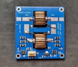
Digital display for Revex W560 directional wattmeter – part 1

The Revex W560 is a dual range VSWR meter that was also sold under other brand names.

W560-01

The low frequency range is specified as 1.8-160MHz.

This project is for an external digital display to suit the low frequency band of the W560. Whilst this project is for a specific meter, the techniques are applicable more widely. Continue reading Digital display for Revex W560 directional wattmeter – part 1

How important is directional coupler Directivity?

How important is coupler Directivity?

Let’s discuss what the term means, and the uncertainty of measurement of DUT VSWR or ReturnLoss due to coupler Directivity.

Coupler performance parameters


Consider the above diagram, when terminated in a matched load, the key performance characteristics are: Continue reading How important is directional coupler Directivity?

AT-100 ATU Sontheimer coupler using a single binocular ferrite core

A reader of my recent article Sontheimer coupler – transformer issues and the follow up articles giving better transformer designs asked whether the coupler use in the popular AT-100 ATU wouldn’t be a good solution.

A quick Google search did not turn up any published design rationale or measurement data for the AT-100 coupler design.

The above circuit is from (Grebenkemper 1987) and is an embodiment of (Sontheimer 1966). In their various forms, this family of couplers have one or sometimes two transformers with their primary in shunt with the through line, and another which is in series with the through line to sense current. To achieve good Directivity, these transformers must be symmetric, nearly ideal, and they must be independent, ie no significant coupling between the transformers by magnetic or electric fields.

The AT-100 uses a Sontheimer coupler, they are very popular with ham users for perceived better performance, notably better Directivity over a wide frequency range. Continue reading AT-100 ATU Sontheimer coupler using a single binocular ferrite core

ISP programming of the (tr)uSDX – more on SPI

ISP programming of the (tr)uSDX (trusdx) showed that filtering on the MOSI pin in that kit distorted the MOSI signal significantly and suggested a workaround (reducing SCK rate) for reliable programming.

Some correspondence prompts a little more information on the nature of the ATmega328P ISCP signals.

The line protocol used is actually SPI, quite a common protocol.

ISP uses SPI MODE 0 (CPOL=0, CPHA=0), shift out on the falling edge of SCK, and capture input on the rising edge.

Let’s look at a three channel capture of SCK, MOSI and MISO of a AVRDUDE / USBasp driving an Arduino Nano.

The capture shows SCK at around 750kHz rate, the default (-B1) rate for AVRDUDE in this setup. Continue reading ISP programming of the (tr)uSDX – more on SPI

(tr)uSDX – review of the directional coupler ADC design

I noted some online discussions where some people had troubles with the displayed forward and reverse RF power  values, and the calculated SWR.

Some of the reports indicate non-zero RF power values displayed when the transmitter is off, symptoms which direct diagnosis in the first instance to review of the ADC input circuit.

This article reviews the hardware design based on documents as published at the date of this article.

ATmega328P datasheet

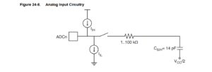
Let’s start by reviewing some relevant parts of the ATmega328P datasheet.

Above is a simplified schematic of the ADC pin input circuit. Note the current sources IIH and IIL. Continue reading (tr)uSDX – review of the directional coupler ADC design

Sontheimer coupler – transformer issues – an alternative design – FT37-43

Sontheimer coupler – transformer issues discussed problems with the Sontheimer coupler in a recently published QRP transceiver ((tr)uSDX / trusdx), suggesting that the core loss in transformer T2 was excessive.

This article presents an alternative design for the transformer for a coupler for a 5W transmitter.

The above circuit is from (Grebenkemper 1987) and is an embodiment of (Sontheimer 1966). In their various forms, this family of couplers have one or sometimes two transformers with their primary in shunt with the through line. Let’s focus on transformer T2. It samples the though line RF voltage, and its magnetising impedance and transformed load appear in shunt with the through line. T2’s load is usually insignificant, but its magnetising impedance is significant and is often a cause of: Continue reading Sontheimer coupler – transformer issues – an alternative design – FT37-43

Sontheimer coupler – transformer issues – an alternative design – FT23-43

Sontheimer coupler – transformer issues discussed problems with the Sontheimer coupler in a recently published QRP transceiver ((tr)uSDX / trusdx), suggesting that the core loss in transformer T2 was excessive.

This article presents an alternative design for the transformer for a coupler for a 5W transmitter.

The above circuit is from (Grebenkemper 1987) and is an embodiment of (Sontheimer 1966). In their various forms, this family of couplers have one or sometimes two transformers with their primary in shunt with the through line. Let’s focus on transformer T2. It samples the though line RF voltage, and its magnetising impedance and transformed load appear in shunt with the through line. T2’s load is usually insignificant, but its magnetising impedance is significant and is often a cause of: Continue reading Sontheimer coupler – transformer issues – an alternative design – FT23-43

ESP WiFi relay project – update #1

ESP WiFi relay project – preview previewed a WiFi controllable relay board using commonly available low cost hardware from sources like eBay and Aliexpress.

The stimulus for the project is a remotely WiFi controllable relay for reset function in a remote controlled ham station, basically to recover operation of some system element by bouncing the power.

The information presented here applies to development v0.2.

Features:

  • support typical multi channel relay boards;
  • ESP8266 and ESP32 firmware versions;
  • WiFi credentials programmable via a captive web interface;
  • DHCP or static IP;
  • mDNS responder;
  • flexible configuration stored as json file in on-board LittleFS file system;
  • optional authentication to secure remote access.


Above is a ESP12F_Relay_30A X2_V1.1 relay board (~$20 inc shipping) deployed for field testing. This board has a switched mode power supply on board and will run on 7-28VDC. In this application, the AC circuit is wired through the NC contacts, and the relays are operated to break the power. Normal operation is with the relays released, and current consumption @ 13.8V is 30mA. Continue reading ESP WiFi relay project – update #1

WriteOptiBoot.bat

I have lots of projects across a range of microcontroller architectures where reliably programming a new instance of the target is required.

Using an IDE to compile and load, eg traditional / common use of the Arduino IDE, is not a path to that reliability.

A better approach is to save compiled binaries, and have a saved method of programming the chip, binary application code, EEPROM if needed, and hardware settings such as fuse bits, options etc.

Let’s look at an example,  a cmd file or bat file to program certain Arduino architecture boards with a customised Optiboot bootloader. Continue reading WriteOptiBoot.bat