A 1:1 RF transformer for measurements – based on Noelec 1:9 balun assembly

The Noelec 1:9 balun (or perhaps Chinese knock off) is available quite cheaply on eBay and provides a good hardware base for a 1:1 version.

Above is a modified device with the original transformer replaced with a Macom ETC1-1T-2TR 1:1 transformer. The replacement is not exactly the same pads, but it is sufficiently compatible to install easily.

The most notable departure from ideal of these small transformers is leakage inductance of 50nH give or take. Continue reading A 1:1 RF transformer for measurements – based on Noelec 1:9 balun assembly

The devil is in the detail – real world transmission lines and loss under standing waves

We are traditionally taught transmission line theory starting with the concept of complex propagation constant γ, and that loss in a section of line is \(Loss=20log_{10}( l |\gamma|) dB\) where l is length. That is the ‘one way’ loss in a travelling wave, also the the matched line loss (MLL) (as there is no reflected wave).

There are some popular formulas and charts that purport to properly estimate the loss under standing waves or mismatch conditions, usually in the form of a function of VSWR and MLL, more on this later.

Let’s explore theoretical calculations of loss for a very short section of common RG58 at 3.6MHz with two different load scenarios.

The scenarios are:

  • Zload=5+j0Ω (VSWR50=10); and
  • Zload=500+j0Ω (VSWR50=10).

Above is the RF Transmission Line Loss Calculator (TLLC) input form. A similar case was run for Zload=500Ω. Continue reading The devil is in the detail – real world transmission lines and loss under standing waves

The devil is in the detail – real world transmission lines and ReturnLoss

We are traditionally taught transmission line theory starting with the concept of complex propagation constant γ and then dealing with them as lossless lines (means Zo is purely real) or low loss distortionless lines (means Zo is purely real).

Let’s explore theoretical calculations of ReturnLoss for a very short section of common RG58 at 3.6MHz.

By definition, \(ReturnLoss=\frac{ForwardPower}{ReflectedPower}\) and it may be expressed as \(ReturnLoss=10log_{10}\frac{ForwardPower}{ReflectedPower} dB\).

The scenarios are:

  • open circuit termination; and
  • short circuit termination.

Above is the RF Transmission Line Loss Calculator (TLLC) input form. Note that it will not accept Zload of zero or infinity, instead a very small value (1e-100) or very large value (1e100) is used. Continue reading The devil is in the detail – real world transmission lines and ReturnLoss

Measurement of recent ‘FT240-43’ core parameters

This article reports measurement of two ‘FT240-43’ cores (actually Fair-rite 5943003801 ‘inductive’ toroids, ie not suppression product) purchased together around 2019, so quite likely from the same manufacturing batch. IIRC, the country of origin was given as China, it is so for product ordered today from element14. The measurements are of 1t on the core, with very short connections to a nanoVNA OSL calibrated from 1-50MHz.

Above, the measurement fixture is simply a short piece of 0.5mm solid copper wire (from data cable) zip tied to the external thread of the SMA jack, and the other end wrapped around the core and just long enough to insert into the inner female pin of the SMA jack. Continue reading Measurement of recent ‘FT240-43’ core parameters

nanoVNA – RG6/U with CCS centre conductor MLL measurement

In my recent article RG6/U with CCS centre conductor – shielded twin study I made the point that it is naive to rely upon most line loss calculators for estimating the loss of this cable type partly because of their inability to model the loss at low HF and partly because of the confidence one might have in commonly available product. In that article I relied upon measured data for a test line section.

I have been asked if the nanoVNA could be bought to bear on the problem of measuring actual matched line loss (MLL). This article describes one method.

The nanoVNA has been OSL calibrated from 1-299MHz, and a 35m section of good RG6 quad shield CCS cable connected to Port 1 (Ch0 in nanoVNA speak).

A sweep was made from 1-30MHz with the far end open and shorted and the sweeps saved as .s1p files.

Above is a screenshot of one of the sweeps. Continue reading nanoVNA – RG6/U with CCS centre conductor MLL measurement

RG6/U with CCS centre conductor – shielded twin study

Some online experts advise the use of synthesised shielded twin instead of ordinary two wire line for HF antennas claiming it is vastly superior.

Now it could be vastly superior for several reasons in all, but let’s focus on just one important parameter, loss under mismatch conditions.

The scenario then is the very popular 132′ multi band dipole:

  • the famous 40m (132′) centre fed dipole;
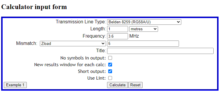
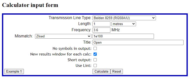
  • 20m of feed line being parallel RG6/U CCS quad shield with shields bonded at both ends;
  • 7MHz where we will assume dipole feed point impedance is ~4000+j0Ω.

We will consider the system balanced and only deal with differential currents.

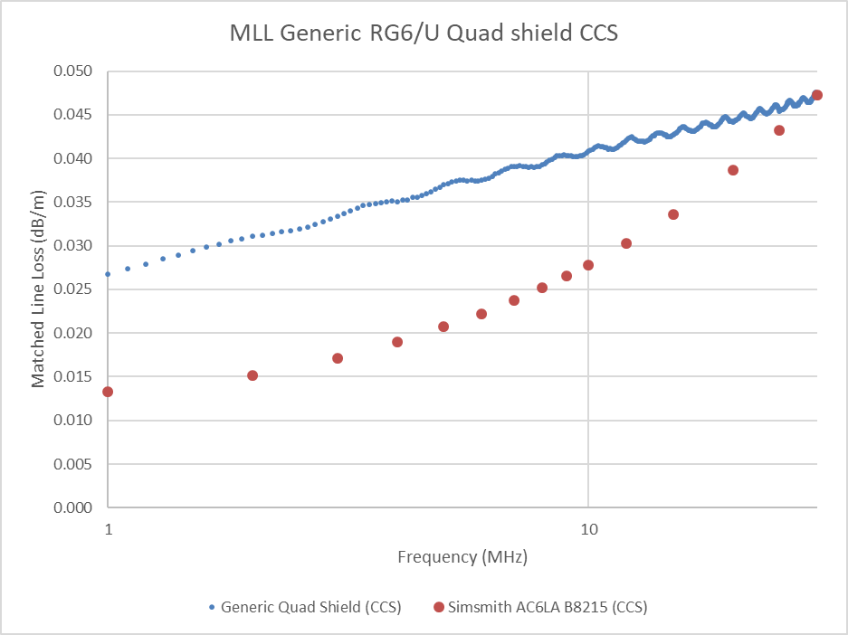
Now rather than depend on loss calculators, most of which don’t reconcile with measurement of CCS RG6/U, I will used measured loss. RG6/U with CCS centre conductor at HF gives a chart of measured loss of a sample of commercial grade CCS quad shield coax.

Above is a comparison of matched line loss (MLL) based on measurement of a length of RG6/U Quad Shield CCS cable and prediction from Simsmith of Belden 8215 (also CCS). The ripple is due to measurement system error, measurements were made quite some years ago with a AIMuhf. Continue reading RG6/U with CCS centre conductor – shielded twin study

nanoVNA – measuring cable velocity factor – demonstration – open wire line

The article nanoVNA – measuring cable velocity factor – demonstration demonstrated measurement of velocity factor of a section of coaxial transmission line. This article demonstrates the technique on a section of two wire copper line.

A significant difference in the two wire line is that we want the line to operate in balanced mode during the test, that there is insignificant common mode current. To that end, a balun will be used on the nanoVNA.

Above, the balun is a home made 1:4 balun that was at hand (the ratio is not too important as the fixture is calibrated at the balun secondary terminals). This balun is wound like a voltage balun, but the secondary is isolated from the input in that it does not have a ‘grounded’ centre tap. There is of course some distributed coupling, but the common mode impedance is very high at the frequencies being used for the test. Continue reading nanoVNA – measuring cable velocity factor – demonstration – open wire line

ESP32 WROOM32 – A possible fix for failure of auto-program facility

Espressif’s esptool has a facility to automatically put the ESP32 into bootloader mode using the DTR and RTS signals of the serial interface.

For whatever reason, it is very unreliable. There are many schematics of knockoffs of Espressif’s original DevKits.

Above is the schematic of one of the larger makers of ESP32 modules, AI-Thinker. The auto-program facility is implemented in the logic gate arrangement at right top of the left top block. Continue reading ESP32 WROOM32 – A possible fix for failure of auto-program facility

Battery contact corrosion on digital calipers

Corrosion of battery contacts in all manner of things due to leakage from the batteries is a growing problem as we seem to accumulate more and more devices that contain batteries and it becomes a chore to replace batteries by their expiry date.

Replacing batteries by their expiry date does not guarantee freedom from leakage related corrosion. The battery market is flooded with counterfeit product and it is hard to know what is genuine, even from apparently reputable suppliers.

Above is a cheap Chinese digital caliper that was damaged by leakage from a brand name (Duracell) SR44 cell. The characteristic green residue has been cleaned from the positive contact with an alcohol soaked cotton bud, and then the contact scratched with a Burgeon 2834C fibre glass scratch brush (below) to remove remaining corrosion products whilst vacuuming to extract as much of the residue as possible. Again, a wipe with a clean alcohol soaked cotton but leaves the contact as clean as practicable. These scratch brushes are extremely effective, one needs to avoid over use which removes more plating than desirable. Continue reading Battery contact corrosion on digital calipers

Working a common mode scenario – VK2OMD – voltage balun solution

Recent articles Working a common mode scenario – G3TXQ Radcom May 2015 and Working a common mode scenario – G3TXQ Radcom May 2015 – voltage balun solution analysed a three terminal equivalent circuit for G3TXQ’s antenna system based on his measurements. Solutions were offered for the expected common mode current with no balun, with a medium impedance common mode choke (current balun) and an ideal voltage balun.

In summary, though G3TXQ expected the antenna system to have good balance, on measurement it was not all that good. The analysis showed that even a moderate impedance common mode choke reduced the common mode current Icm substantially more than no balun, or an ideal voltage balun.

This article performs similar analysis of the case of an ideal voltage balun applied to my own antenna system documented at Equivalent circuit of an antenna system at 3.6MHz.

In this article I will use notation consistent with (Schmidt nd).

Above is the equivalent circuit. Continue reading Working a common mode scenario – VK2OMD – voltage balun solution