Effect of ground on HF horizontal dipole efficiency – more detail

This article expands on Effect of ground on HF horizontal dipole efficiency with some more model detail for the technically minded. See the original article for model details and discussion.

Clip 160

Above is the efficiency curve expanded to 80m height, about 2λ. The graph assumes no matching loss (mismatch loss, changed line loss). efficiency may be significantly poorer if not matched efficiently. Continue reading Effect of ground on HF horizontal dipole efficiency – more detail

Transmit performance of 2m hand held transceivers – absolute gain estimates

Transmit performance of 2m hand held transceivers reported relative field strength measurements for some transceiver / antenna combinations.

This article documents a more careful measurement of the absolute field strength of one combination, and application of that knowledge to the other results.

Measurements of field strength were done with Lou Destefano’s (VK3AQZ) VK3AQZ RF power meter (RFPM1) and a small loop antenna.

RFPM1-10

Above, the RFPM1 RF power meter.

VhfUhfLoopAbove is the small loop used for field strength measurement. It is 2mm hard drawn round copper wire formed into a circle 185mm in circumference, and a common mode choke is used to connect the loop to the RFPM1 power sensor. The common mode choke is 0.6m of RG58C/U with 0.5m of ferrite sleeves over it and its loss is accounted for in the “Other Loss” item.
Continue reading Transmit performance of 2m hand held transceivers – absolute gain estimates

An interesting case study – in service evaluation of coax loss

A poster sought advice of the forum experts about in service evaluation of the loss of some coax feed lines…

Has anyone tested old coax cable to see if the loss increased over time? I just tested two different coax cables at 146 Mhz with the use of a Bird Model 43 Wattmeter. Power measurements were taken at the input of each cable followed by the output. The load in both cases was a 146 Mhz Ground Plane.

The test results seem to show losses similar to new coax although Berk-Tek foam coax may have had a lower loss when new.

1. Berk-Tek 6211 RG-8X Ultra Flex Foam Coax – 68 feet

Measured 25 watts in and 11.7 watts out which represents a 3.3 db loss. …

Assuming that the stated measured power is in fact the indicated forward power on the Bird 43 directional wattmeter and given that the actual Zo of the line should be very close to the calibration impedance of the Bird (50+j0Ω), then the Matched Line Loss (MLL) is very close to 10*log(PfIn/PfOut)=10*log(25/11.7)=3.3db which is significantly above the expected 2.6dB for ‘ordinary’ RG-8/X and warrants re-measurement as it suggests that the cable might have degraded a little. In fact, the OP later reports 10.7W out for 25W in which is MLL of 3.7dB against spec of 2.6dB… a more convincing case for replacement! Continue reading An interesting case study – in service evaluation of coax loss

Matching a quarter wave monopole with two variable caps

Two recent correspondents have discussed matching a quarter wave monopole with two variable caps.

Two capacitor shunt/series match

The matching scheme involves a shunt variable cap at the end of the coax feed line, and a series variable cap to the monopole base. The radials are of course connected to the feed line shield.

This type of matching scheme requires that the monopole feed point has sufficient +ve reactance, ie the monopole is longer than resonant. Lets assume the R component of feed point Z is 35Ω.

This scheme incorporates the simple shunt match, and the value of the shunt capacitor can be found knowing the R value to be matched to 50Ω.

Screenshot - 08_07_2015 , 06_43_07

Above is a Smith chart of a model of the match at 14MHz. The monopole has been lengthened to have 100Ω reactance along with 35Ω resistance. In this case a series cap of 148pF and shunt cap of 150pF are required. Continue reading Matching a quarter wave monopole with two variable caps

Transmit performance of 2m hand held transceivers

This article documents measurements of transmit performance of three hand held 2m radio with several antennas.

Measurements of field strength were done with Lou Destefano’s (VK3AQZ) VK3AQZ RF power meter (RFPM1) and a small loop antenna.

RFPM1-VhfLoop

Above, the field strength meter, a RFPM1 with small loop antenna oriented for max gain in the direction of the DUT.  The instrument reads -73.5dBm with no signal, -69.5dBm with the strongest transmitter with the loop removed, and around -30dBm for the various transmitters with the loop in place… so the meter reading is predominantly due to the loop mode pickup.

All three transmitters have different power. The table below reports power into a 50Ω load and does not take account of mismatch with the various antennas.

Screenshot - 06_07_2015 , 12_53_56

Above a comparison of the configurations on a field strength test at 1λ. The relative column factors the different transmitter power and FS to obtain  a comparative figure independent of power. Mismatch is almost certainly a significant part of the explanation of different performance, but it is quite difficult to measure in this sort of application without disrupting the DUT.

BoafengINF641Antenna

It is interesting that there is little difference observed with the Baofeng on two different antennas, when the Boafeng antenna is clearly inefficient, see the thermograph above.


Balanced ATUs and common mode current

This Feb 2012 article has been copied by request from my VK1OD.net web site which is no longer online. The article may contain links to articles on that site and which are no longer available.

Many designs have a ‘balanced output’ or an option of a ‘balanced output’, but what does that mean, and are they effective in minimising common mode current in an antenna feed line?

ATUs achieve ‘balanced output’ in one of several ways, the common ones are:

  • a grounded impedance transformation network followed by an internal voltage balun;
  • a grounded impedance transformation network followed by an internal current balun;
  • a current balun followed by a symmetric impedance transformation network that may or may not be directly grounded at its centre;
  • a link coupled ATU where the output circuit is symmetric and may or may not be directly grounded at its centre.

Much has been written about the merits of one approach or another, mostly qualitative and often subjective, but there is little in the way of quantitative analysis of the impedance that the ATU offers to common mode current. Continue reading Balanced ATUs and common mode current

Differential and common mode components of current in a two wire transmission line

A pair of conductors in proximity of some other conductors or conducting surface (such as the natural ground) can operate in two modes simultaneously, differential mode and common mode.

Differential mode is where energy is transferred due to fields between the two conductors forming the pair, and common mode is where energy is transferred due to fields between the two conductors forming the pair together and another conductor or conducting surface.

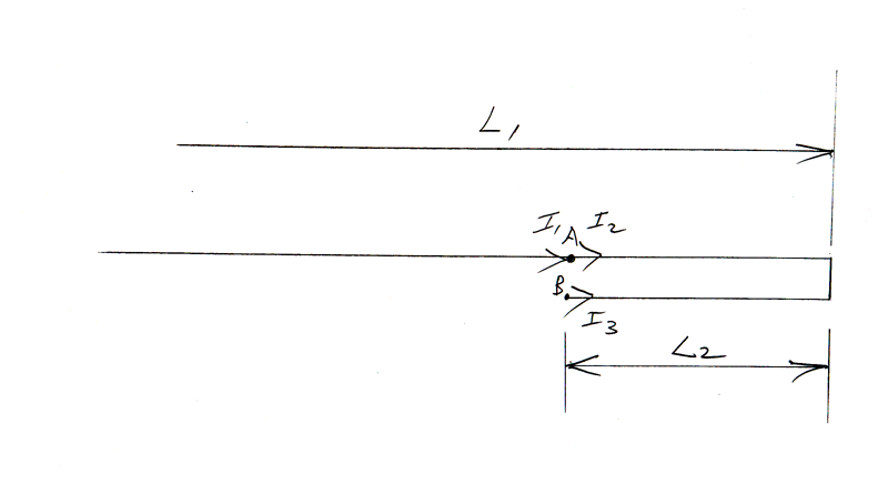
The currents flowing in the two conductors at any point can be decomposed into the differential and common mode currents.

Differential current Id is the component that is equal but opposite in direction, it is half the difference in the two complex line currents I1 and I2.

Common mode current Ic is the component of the line currents common to both conductors, it is half the sum of I1 and I2.

  • Id=(I1-I2)/2
  • Ic=(I1+I2)/2
  • I1=Ic+Id
  • I2=Ic-Id

So, for example, if I1=2A and I2=-1A, Id=(2–1)/2=1.5A, Ic=(2-1)/2=0.5A.

A line that is operating with perfect current balance has only differential current, ie common mode current is zero. It is unlikely that a feed line in a practical antenna system is perfectly balanced, but with due care, it can have very low common mode current, 20dB or more less than the differential component.

Using the AIM to measure matched line loss

A correspondent wrote seeking explanation of difficulty he was having measuring line loss using the advice given in the AIM manual using a scan with either O/C or S/C termination:

Note the one-way cable loss is numerically equal to one-half of the return loss. The return loss is the loss that the signal experiences in two passes, down and back along the open cable.

Because my correspondent was using one of the versions of AIM that I know to be unreliable, I have repeated the measurements on a cable at hand using AIM_900B to demonstrate the situation.

The test cable I have used is 10m of RG58C/U which I expect should have matched line loss (MLL) of 0.26dB, but I expect this to be a little worse as it is a budget grade cable that I have measured worse in the past. Continue reading Using the AIM to measure matched line loss

Antenna span tensioner using a counterweighted halyard

Correspondents have asked about application of the technique used in Antenna span spring tensioner using Antenna wire catenary calculator to a span tensioned with a counterweighted halyard.

The scenarios bear a lot of similarity, the main difference being that the tension from the counterweight is constant up to the point that the counterweight travel reaches its limit.

The tension applied is the weight force of the counterweight with a little increase to allow for friction in the sheave block.

So, lets say the scenario is a 42m wire plus halyard that adds 1m to the span under no wind conditions and can pay out a further 1m at which it reaches its limit. Lets say the counterweight is 5kg weight so 49.0N tension. Continue reading Antenna span tensioner using a counterweighted halyard