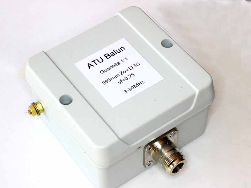
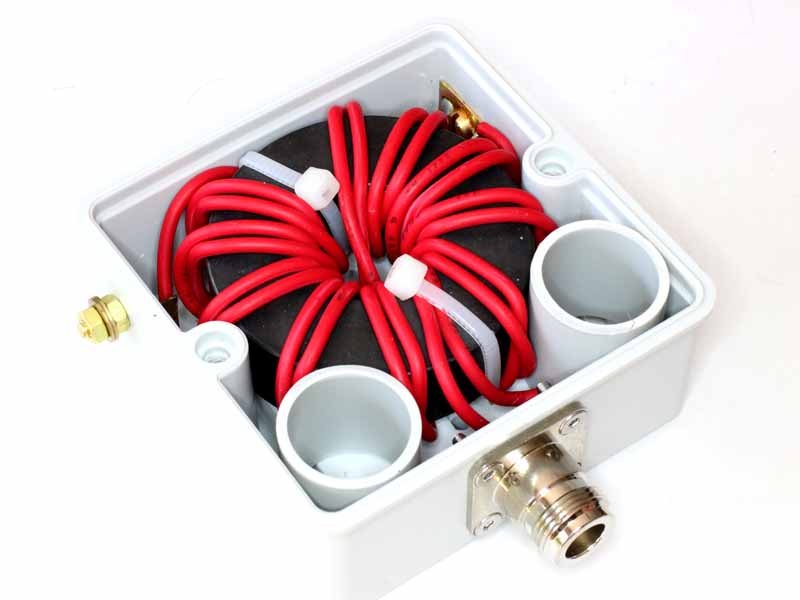
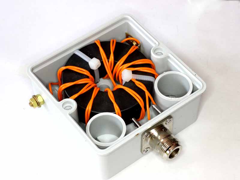
David, VK3IL posted EFHW matching unit in which he describes a ferrite cored transformer matching unit that is of a common / popular style.
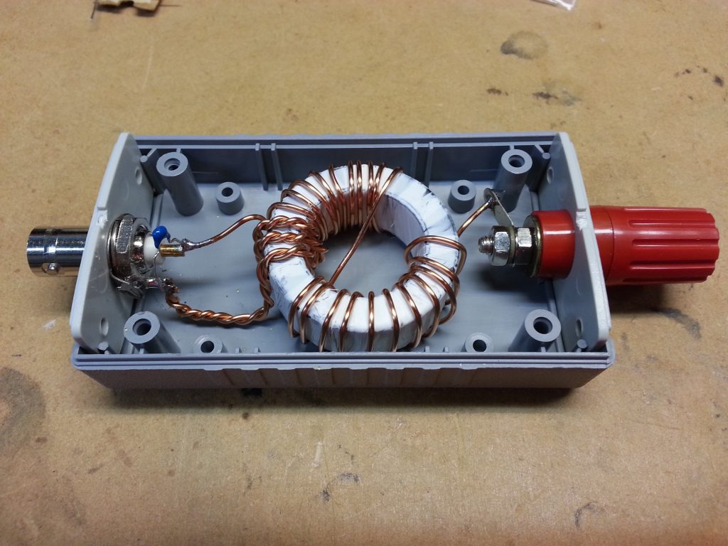
Above is David’s pic of his implementation. It is a FT140-43 toroid with 3 and 24t windings and note the 150pF capacitor in shunt with the coax connector.
The popular belief is that these are a broadband impedance transformer with impedance ratio equal to the square of the turns ratio, 64 in this case and therefore a broad band match from 3200Ω to 50Ω.
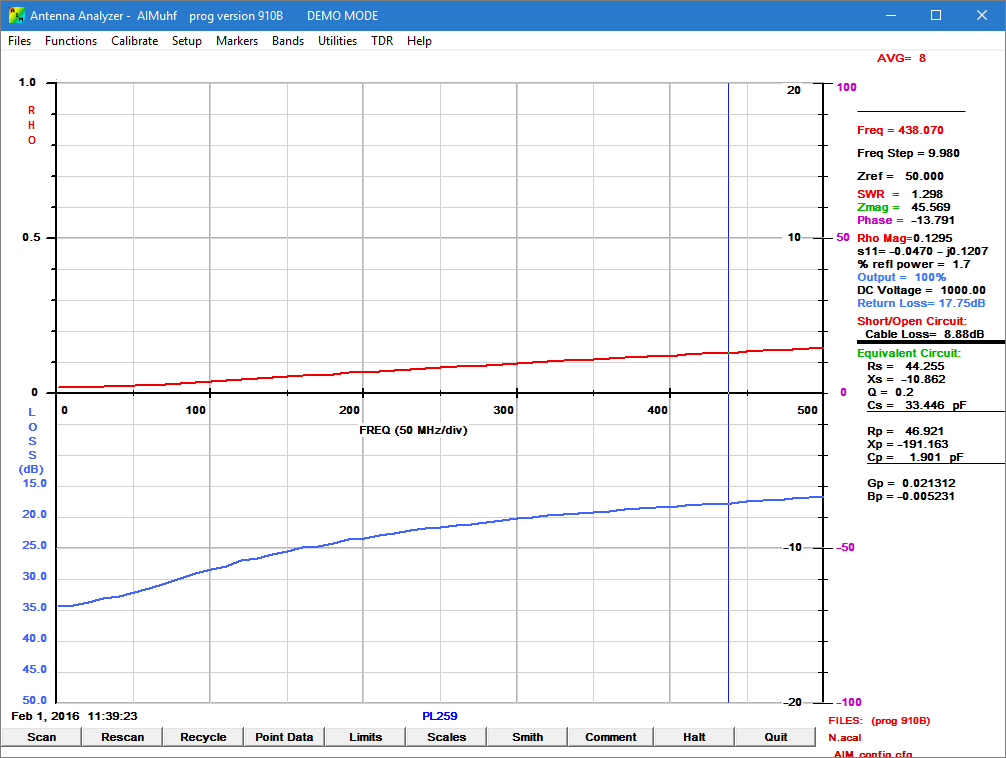
To his credit, David took some measurements of several different variations and reported them in his article.
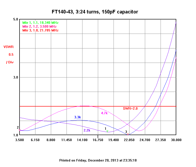
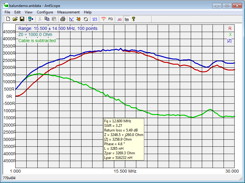
Above are David’s measurements of the subject transformer.
Lets explore the matching detail for the case of a 3.3kΩ load at 22MHz, and using the 150pF shunt cap.
Superficially, you might convince yourself that this is explained by the turns squared story, but the 150pF doesn’t reconcile with that story, nor does the variation with frequency, eg the rapid change above 22MHz. Continue reading End fed matching – analysis of VK3IL’s measurements