Post mortem review of a 144MHz combiner / splitter

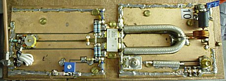
This article is a post mortem review of a 144MHz splitter combiner that was made using RG6 coax. It is post mortem (ie post death) because the combiner was stored outdoors without checking that the connectors were protected from weather.

Fig01

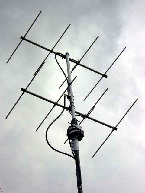
The combiner was used successfully for over 10 years on a 144MHz four over four antenna system (above) without any maintenance problems.

Fig06

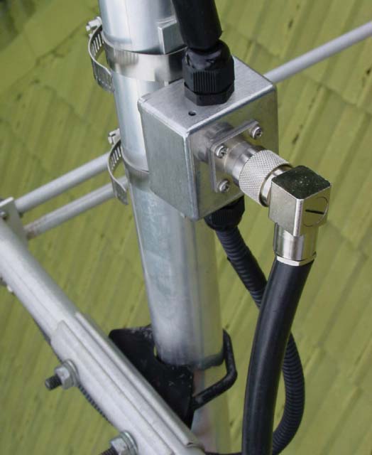
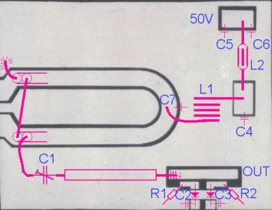
Above is a close up of the Tee point of the network. The coax cables are protected by HDPE sleeving to reduce the chance of damage at the hands of Sulphur Crested Cockatoos, in the event there was no damage.
Continue reading Post mortem review of a 144MHz combiner / splitter

Tuning combiner lines

A common method of combining two 50Ω antennas to a single 50Ω feed is using a quarter wave transformer using 75Ω line from the common feed point to each antenna.

A recent posting to one of the ham fora raises the posters problems with making this really simple feed system work.

Screenshot - 25_08_16 , 07_25_16

Above is his measured input characteristic with good 50Ω loads on each leg. Reading a hundred posts, it seems that he attributes this to legs of 0.167m length of RG11. The problem is that RG11 as most of us know it has a solid PE dielectric giving it a vf=0.66 and that 0.167m is 63° at 207MHz… so why the response above. Continue reading Tuning combiner lines

Exploiting your antenna analyser #23

Seeing recent discussion by online experts insisting that power relays are not suitable to RF prompts an interesting and relevant application of a good antenna analyser.

Screenshot - 03_08_16 , 14_12_56

Above is a sweep of an A/B changeover relay intended for HF application at up to 100W and lowish VSWR. The sweep is actually from 1 to 61MHz to be confident that there is not poor behaviour just outside of the HF range that might present on another implementation of the same design. Continue reading Exploiting your antenna analyser #23

InsertionVSWR of Grebenkemper’s Tandem Match

The findings at InsertionVSWR of Revex W560 on HF and the suggestion that the low frequency problem is characteristic of poorly designed Sontheimer couplers (Sontheimer, C & Frederick 1966).

These couplers were popularised by (Grebenkemper 1987)  in his Tandem Match – An Accurate Directional Wattmeter and have appeared in ARRL handbooks over the decades, and may have inspired the many commercial implementations of the coupler.

Grebenkemper claims his meter is ‘good’ down to 1.8MHz, but does not clearly claim any particular InsertionVSWR. There is limited value in an instrument that can measure down to 1.05 when it causes significantly higher VSWR itself.

Screenshot - 24_07_16 , 15_31_41

Lets drill down on Gebenkember’s article, specifically the coupler design.
Continue reading InsertionVSWR of Grebenkemper’s Tandem Match

Optimal Z0 for TLT sections challenge – a solution

Optimal Z0 for Guanella balun sections left the reader with a though exercise, a transmission line transformer used by PA0V in a 144MHz power amplifier output network.

Clip 206

The pair of tabs to the left are driven by FET drains, the upper pink centre conductor is grounded, the lower end connecting to C1 is the output to a nominal 50R load. The network shown near OUT is for fine load adjustment. There are two coax sections making this TLT, shields bonded all the way around and the centre conductors connected as shown. What is the optimal value of Z0 for each the coax sections?

PAdetail

Above is a pic of the PA, and we are looking at the network to the right of the dual FET. Continue reading Optimal Z0 for TLT sections challenge – a solution

Optimal Z0 for Guanella balun sections

A Guanella balun may have several sections, and they may be connected in parallel on one side and series on the other side so as to achieve nominal impedance transformation ratios other than 1.

The question is often asked, what is the optimal Z0 for these line sections?

Several answers exist in ham lore, but the answer is relatively simple and revealed by the most basic understanding of transmission lines.

If you do not want standing waves on a line section and its associated impedance transformation, then make sure that Z0=V/I… easy as that.

(Guanella 1944) explains it with examples:

Screenshot - 09_07_16 , 15_55_57

Note above that he refers to coil systems. He did not describe for instance (b) on a single core, a shared magnetic circuit which would be a single core system, but he states clearly two coil systems. (Sevick 2001) and lots of other hams say otherwise, but they are wrong. Continue reading Optimal Z0 for Guanella balun sections

Can a hand held analyser be used to evaluate Insertion VSWR of a VSWR meter?

Some recent articles here used a two port analyser to evaluate Insertion VSWR of some coax switches, and it raises the question about application of a hand held analyser and Insertion VSWR of a VSWR meter.

(Duffy 2007) listed tests for evaluation of a VSWR meter:

Testing a VSWR meter

The tests here need to be interpreted in the context of whether the device under test (DUT) has only calibrated power scales, or a VSWR Set/Reflected mode of measurement, and whether directional coupler scales are identical for both directions.

  1. Connect a calibrated dummy load of the nominal impedance on the instrument output and measure the VSWR at upper and lower limit frequencies and some in between frequencies. The VSWR should be 1. (Checks nominal calibration impedance);
  2. Repeat Test 1 at a selection of test frequencies and for each test, without changing transmitter power, reverse the DUT and verify that repeat the forward/set and reflected readings swap, but are of the same amplitude (checks the symmetry / balance of the detectors under matched line conditions).
  3. Connect a s/c to the instrument output and measure the VSWR at upper and lower limit frequencies and some in between frequencies. The VSWR should be infinite. (Discloses averaging due to excessive sampler length);
  4. Connect an o/c to the instrument output and measure the VSWR at upper and lower limit frequencies and some in between frequencies. The VSWR should be infinite. (Discloses averaging due to excessive sampler length);
  5. Connect a calibrated wattmeter / dummy load of the nominal impedance on the instrument output and measure calibration accuracy of power / ρ / VSWR scales at a range of power levels in both forward and reflected directions (Checks scale shape and absolute power calibration accuracy).
  6. Repeating Test 1 additionally with a calibrated VSWR meter connected to the input to the DUT, and measure the VSWR caused by the DUT at a range of test frequencies (Checks Insertion VSWR).

It is not unusual for low grade instruments to pass Test 1, but to fail Test 6 (and some others, especially Test 3 and Test 4) towards the higher end of their specified frequency range.

Item 6 in the list was to evaluate the Insertion VSWR. Continue reading Can a hand held analyser be used to evaluate Insertion VSWR of a VSWR meter?

Coax switches – is shorting unused port necessary for isolation?

At Ratings of coax antenna switches I showed characteristics of a home made switch which has very low InsertionVSWR, but poor isolation.

A couple of correspondents have offered an explanation that the unused port must be shorted to get good isolation.

If that was the case, then we would expect all coax switches that leave the unused port open to have poor isolation.

Let us look at a very good coaxial relay


Above is a Dowkey 402 series relay which has good performance to GHz. It does not short the unused port.
Continue reading Coax switches – is shorting unused port necessary for isolation?