Comparison of R134a and HyChill Minus 30

I am considering replacing the R134a refrigerant in my car aircon system with a hydrocarbon refrigerant. The candidate is Hychill Minus 30 (HC-30).

This article is a limited comparison of the R134a and HC-30 from the point of view of pressure temperature behavior as it impact practical implementation and measurement.

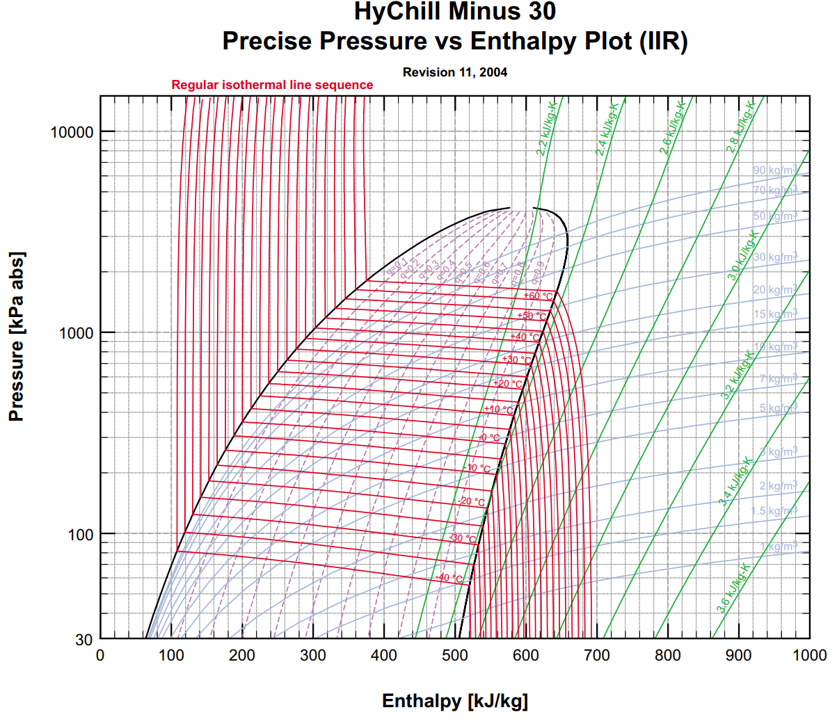
Exploring HyChill Minus 30 laid down the basis of a CoolProp model of HC-30 for comparison with CoolProp model of R134a.

Fig 1

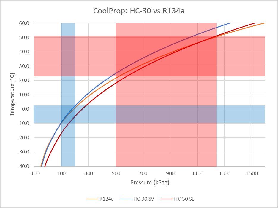
Above is a comparison of the pressure/temperature of HC-30 and R134a over the range of interest in a vehicle aircon. The typical high and low side HC-30 operating pressure bands are shaded. Continue reading Comparison of R134a and HyChill Minus 30

Exploring HyChill Minus 30

I am considering replacing the R134a refrigerant in my car aircon system with a hydrocarbon refrigerant. The candidate is Hychill Minus 30 (HC-30), a Propane and Isobutane mix.

Fig 1

The p-H (pressure enthalpy) chart of HC-30 above was digitised to derive some comparison charts used for this study. The sampling process necessarily introduces some error, and although small, it causes ripples on graphs of some key values. Continue reading Exploring HyChill Minus 30

An interesting case study of measurement of a balun’s Insertion VSWR

Jeff, 2E0CIT, sent me a Rigexpert AA-170 measurement file of his test of Insertion VSWR of a commercial balun.

Insertion VSWR is the VSWR looking into the balun with a matched load (termination) on its output, it is a measure of imperfection of the balun. It ought to be a specification item for low Insertion VSWR baluns, but it rarely given.

A broadband low Insertion VSWR balun must be wound with a transmission line of the nominal impedance, 50Ω in this case, and in the case of 50Ω , it is most likely to be coax.

Above is the initial VSWR plot received. The VSWR response is poorer than one might want in a low Insertion VSWR balun… but to drill down on the reasons, the Smith chart view of the data gives insight. Continue reading An interesting case study of measurement of a balun’s Insertion VSWR

VU3SQM directional wattmeter build – #4

VU3SQM directional wattmeter build – #1 laid out the first steps in design review and build of a directional wattmeter.

At long last, some PTFE rod arrived to permit assembly of the transformers.

For reasons discussed in an earlier article, the transformers use a larger core than the original VU3SQM. They need to stand above the board, and whilst that compromises the mechanical strength of the assembly, it should have better performance. Continue reading VU3SQM directional wattmeter build – #4

VU3SQM directional wattmeter build – #3

VU3SQM directional wattmeter build – #1 laid out the first steps in design review and build of a directional wattmeter.

The parts have arrived and construction commenced.

Above, the PCB populated with the SM parts and soldered. It was soldered in an IR reflow oven. Continue reading VU3SQM directional wattmeter build – #3

VU3SQM directional wattmeter build – #2

VU3SQM directional wattmeter build – #1 laid out the first steps in design review and build of a directional wattmeter.

This article canvasses the issues of the display.

Intention is a digital based display (though not to exclude an analogue meter or bar graph type displays).

So, the output of the AD8307 needs to be digitised.

Let’s first consider the nature of the AD8307.

It is a log detector, so it provides a ‘DC’ voltage proportional to the log of the input signal, but the ‘DC’ voltage can vary very quickly.

The chart above from the AD8307 datasheet shows that the unfiltered response to a burst of RF has a rise time of well under 1µs. Continue reading VU3SQM directional wattmeter build – #2

VU3SQM directional wattmeter build – #1

VU3SQM offers an interesting directional coupler based on a Sontheimer coupler, and using AD8307 power sensing for a nominally HF coupler. I must say that I am not a fan of Sontheimer couplers… but that is what the board uses.

This article lays out a preliminary design review to assist in selection of appropriate toroids, and ordering of the needed parts.

PCB

Above, the top side of a PCB. Continue reading VU3SQM directional wattmeter build – #1

A fourth round with the FA-VA5 antenna analyser

I recently acquired a FA-VA5 antenna analyser.

Before trusting measurements made with any instrument, its behaviour should be validated, and this article documents issues discovered in one thread of tests. The developer does not like the term “defects”, he prefers “issues”, a soft denial of “problems”.

So, the test scenario is the VA5 measuring the impedance looking into a 35m length of RG6 coax with an open circuit at the far end. The VA5 has been SOL calibrated with the higher quality loads sold by SDR-kits, and the test is a 3.5MHz. The firmware is the latest, v1.08 (about 3 months old).

The screenshots are taken with a camera, there does not seem to be a method of uploading screenshots to a PC.

Above is a swept Z measurement just above the half wave resonance of the line section. The impedance at the marker is comparable with that measured using an AA-600, so I would accept that it is probably correct. The graph is another matter. Continue reading A fourth round with the FA-VA5 antenna analyser

A third test of the FA-VA5 antenna analyser

I recently acquired a FA-VA5 antenna analyser.

Whilst preparing A first test of the FA-VA5 antenna analyser, issues were noticed with the user interface design / implementation. I stated in a later article that The matter of the clumsy / unproductive user interface will be explored more at a later time.

This article introduces a short video demonstration of the frustrating / unreliable user interface (UI) in firmware v1.08 where buttons do not seem to operate intuitively and consistently.

The video shows that whilst the up down buttons seem to work reliably and consistently in ‘menu’ mode, they do not do so when trying to adjust the frequency. Continue reading A third test of the FA-VA5 antenna analyser

RFPM2 – calibration files

The RF Power Meter 2 (RFPM2) stores calibration constants in a file located in the (SPIFFS) file system in the microcontroller flash.

The file opened by default when RFPM2 starts is /default.cfg, the following is an example.

{
"name":"dBm",
"hostname":"rfpm201",
"vref":3.3,
"avg":3,
"slope":0.12991,
"intercept":-91.406,
"unit":"dBm",
"lcdfsd":16
}

The parameters above capture the most basic operation of RFPM2 as a power meter directly displaying dBm with bar graph in fixed 2dB increments to 16dBm FSD. These values serve as a basis for some other applications as they capture the basic intercept and slope of the AD8307 module in this instance.

Current probe calibration

Alternative config files can be loaded on the fly from the webserver interface, for example http://192.168.0.86/config?filename=/dBA.cfg will load the dBA config file for a certain current probe. Continue reading RFPM2 – calibration files