LNR Precision small transmitting loop

LNR Precision have announced a small transmitting loop for amateur radio.

This article is a revision to take account of recently updated information published by LNR filling in some of the gaps in their original page. It is encouraging to see better product descriptions and measurement data.

Description

The antenna is described at (LNR Precision 2016).

The loop itself appears to be 3/8 Heliax or similar (nominally 9.5mm outer conductor diameter) in a rough circle of 45″ (1.143m) diameter.

Little information is given of the internals, but the promotional material gives a VSWR curve for a matched antenna at 7.065MHz. To their credit, they give the height above ground and ground type for their tests.

The VSWR=3 bandwidth scaled from the graph is 18kHz.

If we assume for a moment that the VSWR measurement was captured at a substantial height above ground, its behavior approaches that of the antenna in free space. Taking the assumption that the published curve is similar to the antenna in free space, we can estimate efficiency based on earlier assumptions. Such antennas very close to ground have a directivity of about 6dB (dependent on ground parameters), and that can be used with efficiency to estimate gain in proximity to ground.

The assumed values and published VSWR curve indicate an antenna system half power bandwidth of 15.6kHz and Q of 453 which implies efficiency of 2.8%.

The actual value for radiation resistance is likely to be with -50-+100% of the free space value used, and that rolls up as an uncertainty of +/-3dB in the calculated efficiency and gain. Continue reading LNR Precision small transmitting loop

Current and voltage implications of a small transmitting loop power ratings

This article gives a simple method for calculating the key voltage and current in a small transmitting loop using observed or expected behaviour and Calculate small transmitting loop gain from bandwidth measurement.

Method

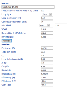
Above is a model hypothetical 1m diameter loop of 10mm conductor on 40m with 1% radiation efficiency.

Lets say it is rated for input power being the lesser of 10W continuous, or 30W PEP SSB. Continue reading Current and voltage implications of a small transmitting loop power ratings

CHA P-Loop 2.0 small transmitting loop

Chameleon have released their CHA-P-Loop 2.0 small transmitting loop. This article considers the likely efficiency on 40m based on their published measurements and Efficiency and gain of Small Transmitting Loops (STL).

Description

The antenna is described at http://chameleonantenna.com/CHA%20P-LOOP%202.0/CHA%20P-LOOP%202.0.html.

This analysis does not consider the proprietary Power Compensator option for lack of sufficient information.

The loop itself appears to be LMR400 coax or similar (nominally 8.0mm outer conductor diameter) in a rough circle of 34″ (0.863m) diameter.

Little information is given of the internals, but the promotional material gives a VSWR curve for a matched antenna at 7.15MHz. To their credit, they give the height above ground and ground type for their tests, though elevation above ground was between 1/2 diameter to a full diameter of the P-LOOP 2.0 is a little vague.

Basic loop (34″)

The VSWR=3 bandwidth scaled from the graph is 27.0kHz. The shape of the curve near minimum suggests that were the scan points sufficiently close, the minimum VSWR would be very close to 1.0 and it is taken as 1.0.

If we assume for a moment that the VSWR measurement was captured at a substantial height above ground, its behaviour approaches that of the antenna in free space. Taking the assumption that the published curve is similar to the antenna in free space, we can estimate the gain and efficiency based on earlier assumptions.
Continue reading CHA P-Loop 2.0 small transmitting loop

80m half wave dipole made from 0.91mm steel MIG wire

Hams being innovative come up with a myriad of cheap alternatives for wire for antennas. One of those alternatives is common 0.91mm steel MIG wire.

Steel MIG wire is often coated with copper and is claimed by some online experts to “work real good”, particularly as a stealth antenna.

But is it the makings of a reasonably efficient antenna?

This article applies the model developed at A model of current distribution in copper clad steel conductors at RF to estimate the effective RF resistance of the wire at 3.5MHz.

Copper coated round steel conductor (MIG wire) – 0.91mm single core

In fact copper is an undesirable and restricted contaminant of steel welding wire, high grade MIG wire is not copper coated.

Copper content is held to less than 0.05% in the core, and less than 0.05% in the coating… which on my calcs says the coating of common 0.91mm MIG wire is less than 0.125µm…. basically it is a small diameter wire with low conductivity and high permeability. Continue reading 80m half wave dipole made from 0.91mm steel MIG wire

80m half wave dipole made from galvanised fence wire

Hams being innovative come up with a myriad of cheap alternatives for wire for antennas. One of those alternatives is galvanised steel fence wire.

A small roll of galvanised tie wire can be purchased from Bunnings hardware for about $10 for 95m… so at $0.10/m it looks like an economical solution.

But is it the makings of a reasonably efficient antenna?

This article applies the model developed at A model of current distribution in copper clad steel conductors at RF to estimate the effective RF resistance of the wire at 3.5MHz.

Galvanised round steel conductor – 1.5mm single core

A sample of new unweathered wire was measured to determine the approximate zinc coating depth, it was 15µm. Note that zinc is a sacrificial coating and it will erode through life, so this study is an optimistic one of wire when new. Continue reading 80m half wave dipole made from galvanised fence wire

Skin depth in copper at 1.8MHz according to QRZ

Having just written again on skin effect and copper clad steel (CCS) conductors on HF, and the potential for less than copper performance, it was interesting to note a thread on QRZ where the OP asked for advice on the issue with budget CCS RG-11.

Two late posts as I write this were:

There really is no real issue with skin effect on HF bands with copper clad materials.

and…

At 1.8 MHz, the skin depth in copper is 0.654 micro-meters (.0000654 mm), so the copper cladding on the center conductor of most RG-11 type coaxial cables is more than sufficient for any of our current bands.

The specific advice above looks interesting, convincing even… but thankfully, the skin depth in copper is nowhere near either of the figures he gave. Continue reading Skin depth in copper at 1.8MHz according to QRZ

Reconciliation of Duffy CCS model with N7WS ladder line measurements

In developing and implementing A model of current distribution in copper clad steel conductors at RF reconciliation against some other published data was important.

(Stewart 1999) published a set of measurements of the popular Wireman windowed ladder line products. His measurements were in the range 50-150MHz. They form the basis for most calculators on quantitative analyses at HF, despite the fact that it is a dangerous extrapolation for CCS construction.

Nevertheless, the directly stated measurements at 50MHz are a useful calibration point for reconciliation.

Above is Table 1 from Stewart, it sets out measurements of four Wireman m.products and a plain copper line.

The table below compares Stewart’s measurements with the CCS model and with TLDetails results (where available). Continue reading Reconciliation of Duffy CCS model with N7WS ladder line measurements

A model of current distribution in copper clad steel conductors at RF

A model for current distribution in a conductor is that for a homogenous conducting half space with surface current parallel to the interface. Current density at depth d is given by the expression \(J=J_0 \cdot e^{(-(1+\jmath ) \cdot \frac dδ)}\) where δ is the skin depth \(δ=(ω \cdot µ \cdot σ)^{0.5}\), σ is the conductivity). This is a model for a plane wave in an infinite block of conductor, so there are some issues caused by curvature of the wire surface, more so towards the centre.

Copper round conductor – 1.024mm (#18) single core

Fig 1:

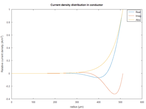
Fig 1 is a plot of the current distribution in a 1mm dia (#18) round copper conductor at 1.8MHz as implied by the model. Note that while the magnitude of current decays exponentially with depth, there is an imaginary component that hints a curl of the E and H fields within the conductor. Continue reading A model of current distribution in copper clad steel conductors at RF

QRP quarterly on small transmitting loop efficiency

A correspondent recently wrote regarding the theory expounded in (Findling et al 2012), and their measurements and performance predictions of the AlexLoop Walkham, Portable Magnetic Loop Antenna by PY1AHD.

The authors give a formula for lossless Q (to mean no loss other than by radiation) without explanation or justification.

The formula is wrong, possibly a result of slavish acceptance of Hart’s two factor incorrectly applied (see Duffy 2015, and Antennas and Q). This error feeds into an optimistic estimate of antenna efficiency.

Analysis of measurement data

(Findling et al 2012) presents a table of measured half power bandwidth for the Alexloop.

Taking the 40m case, lets calculate to Q for a lossless loop, Qrad in Findling’s terms.

Note that Q for the lossless loop is about half that of Findling. Continue reading QRP quarterly on small transmitting loop efficiency

Workup of G5RV inverted V using high strength aluminium MIG wire

This article is a workup of replacement of my 2mm HDC G5RV and feedline with high strength 1.6 aluminium MIG wire to evaluate practical issues with use of an aluminium conductor.

The G5RV configuration is an inverted V, and although half a G5RV is 15m, the supports result in a 20m length of wire to the support. The configuration has a central support and simple spans for each leg of the G5RV to their respective supports. Continue reading Workup of G5RV inverted V using high strength aluminium MIG wire