Checkout of a roll of Commscope 4510404 CCS RG11A/U – Zoc, Zsc based MLL calculation

Checkout of a roll of Commscope 4510404 CCS RG11A/U documented a simple and quick test of the matched line loss (MLL) of a roll of new RG11A/U just delivered. The test used is simple, and quite suited to the case where the far end of the cable is not accessible, eg buried inside the drum.

In this case, the far end of the cable was accessible and a series of measurements of impedance with a short and open termination could be made. This is a more comprehensive test, but involves more complicated calculations. Continue reading Checkout of a roll of Commscope 4510404 CCS RG11A/U – Zoc, Zsc based MLL calculation

Checkout of a roll of Commscope 4510404 CCS RG11A/U

I saw an eBay listing for 305m (1000′) rolls of Commscope 4510404 CCS RG11A/U which looked interesting, time for some due diligence.

Being a brand name product, specifications were probably available and indeed were quickly found.

The cable is a CCS RG11A/U (Zo=75Ω), and from the centre conductor DC resistance value (12.5Ω/305m) and 1.63mm (#14) size, it appeared likely that it was 21% IACS Copperweld, and that the cladding thickness should be 49µm. At that copper thickness, near copper like performance was likely down to perhaps 7MHz (where it is 2 skin depths thick).

A roll was ordered as it was likely to be quite usable cable and at $99 including shipping (~25kg) it should be good value. Continue reading Checkout of a roll of Commscope 4510404 CCS RG11A/U

A walkthrough of using a Rigexpert AA-600 to make a quick measurement of loss of a new roll of CCS RG11

The technique is to make a measurement near to the frequency of interest of Rin at resonance of the length of line with open circuit at the far end, and to calculate the matched line loss (MLL) using Calculate transmission line Matched Line Loss from Rin of o/c or s/c resonant section.

Let’s demonstrate the measurement of Rin of an o/c resonant section around the 160m band, which we will then use to calculate MLL.

Above, the AA-600 connected to the cable using a F(F)-N(M) adapter, the cable is 305m in length and the far end is open circuit. Continue reading A walkthrough of using a Rigexpert AA-600 to make a quick measurement of loss of a new roll of CCS RG11

A model of current distribution in copper clad steel conductors at RF – comparison with Severns 2000

A model of current distribution in copper clad steel conductors at RF described a simple analytical model. This article compares the results of that model with graphs published in (Severns 2000) and is of particular interest since Severns used an FEA based model.

Above is Fig 3A from Severns and is the current distribution at 1MHz for 20.3µm (0.0008″) cladding of a 0.405mm (#26) CCS (Copperweld) conductor. Continue reading A model of current distribution in copper clad steel conductors at RF – comparison with Severns 2000

High and low Z responses of a resonant / antiresonant shorted / open transmission line section

At KB1CKT measurement of a roll of RG6/U I stated:

The technique he followed was to make a series of measurements of Rin at low Z resonances of the length of line with open circuit at the far end, and to calculate the MLL using Calculate transmission line Matched Line Loss from Rin of o/c or s/c resonant section.

Though the calculator can use high Z resonances, the high Z resonances are very narrow and it is very difficult to measure Rin at the true resonant frequency. So, only his reported low Z measurements will be used.

This article illustrates the response expected from a 13.7m length of Belden 8262 (RG58C/U). Continue reading High and low Z responses of a resonant / antiresonant shorted / open transmission line section

KB1CKT measurement of a roll of RG6/U

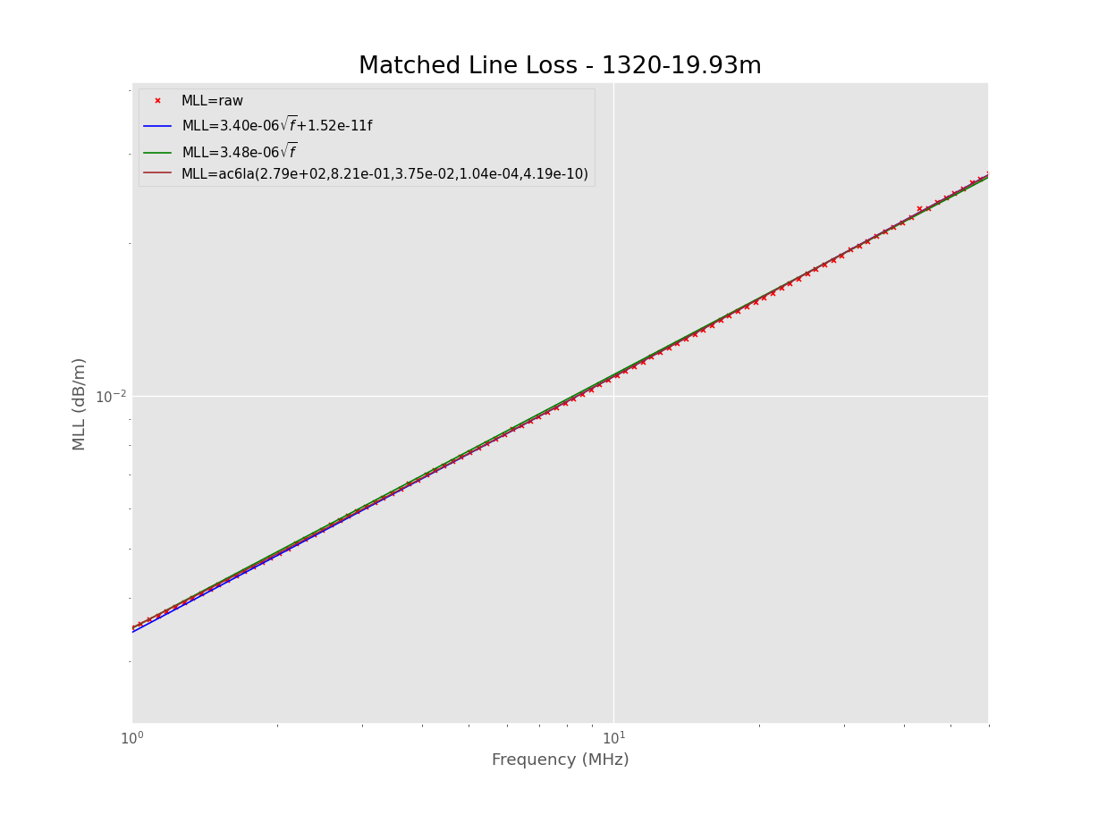
Shawn, KB1CKT, set about measuring the matched line (MLL) loss of a roll (~152.4m) RG6/U on the roll and published his results in an online discussion.

A word of warning: measuring on the roll can give unusual results if the cable is deformed significantly on the roll. A higher risk for foamed dielectric cables, and this is one of that type.

The technique he followed was to make a series of measurements of Rin at low Z resonances of the length of line with open circuit at the far end, and to calculate the MLL using Calculate transmission line Matched Line Loss from Rin of o/c or s/c resonant section.

Impedance measurements were made using a nanoVNA which was OSL calibrated in several ranges through the series of measurements. Also notable was that there were several coax adapters used to connect the RG6 to VNA.

Though the calculator can use high Z resonances, the high Z resonances are very narrow and it is very difficult to measure Rin at the true resonant frequency. So, only his reported low Z measurements will be used.

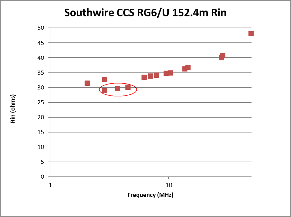
So. let’s graph the measured Rin at zero crossing of Xin.

The circled measurements appear out of line with the others. They were made with a different OSL calibration that the ones immediately below and above, so that hints something may have gone wrong in the calibration. Two of the possible explanations are: Continue reading KB1CKT measurement of a roll of RG6/U

Loss of ladder line: copper vs CCS (Seminole 1320 vs 1321) – KN5L’s measurements

John, KN5L, has published measurements made of two types of nominally 300Ω windowed ladder line. The measurements of such similar lines gives opportunity to explore the effect of conductor differences on matched line loss (MLL).

Above is an analysis of KN5L’s published measurements of a 19.93m test section of Seminole 1320 (nominal 300Ω windowed ladder line, 0.812mm (#20) 7 strand copper). The line was purchased around 2015. The plot has: Continue reading Loss of ladder line: copper vs CCS (Seminole 1320 vs 1321) – KN5L’s measurements

Loss of ladder line: copper vs CCS (DXE-LL300-1C) – KN5L’s measurement 11/2020

DXE sell a nominal 300Ω ladder line, DX Engineering 300-ohm Ladder Line DXE-LL300-1C, and to their credit they give measured matched line loss (MLL) figures.

Loss of ladder line: copper vs CCS (DXE-LL300-1C) – revised for 25/07/2018 datasheet was a revision of an earlier article based on an updated datasheet from DXE. I noted that the specification data had artifacts that one would not expect of such a line, and I questioned whether the datasheet was credible.

John, KN5L, recently purchased, measured and published measurements of a 10.06m (33′) section of new DXE-LL300-1C which provide an independent dataset that might cast some light on the matter.

The chart above plots:

  • DXE’s datasheet MLL figures (converted to dB/m);
  • MLL calculated from KN5L’s S11 open and shorted measurements; and
  • theoretical MLL for round copper conductors of the same gauge as specified for the LL300 (dielectric loss is assumed insignificant).

Continue reading Loss of ladder line: copper vs CCS (DXE-LL300-1C) – KN5L’s measurement 11/2020

A low cost two wire transmission line using high strength aluminium MIG wire and agricultural trellis clips

This article documents a weather test on a trial section of two wire line using:

  • 1.6mm 5356 Aluminium MIG wire;
  • agricultural clips (Trellis Clips, Rose Clips) found on eBAY.

Construction

Above is a pic of the Rose Clip as a line insulator / support. The clips are pretty flimsy but pretty cheap. They click onto the 1.6mm diameter wire reasonably firmly. Continue reading A low cost two wire transmission line using high strength aluminium MIG wire and agricultural trellis clips

RG6/U with CCS centre conductor – shielded twin study – why is it so lossy?

RG6/U with CCS centre conductor – shielded twin study discussed a synthesised synthesised shielded twin instead of ordinary two wire line for an example HF multiband antenna.

The original scenario then is the very popular 132′ multi band dipole:

  • the famous 40m (132′) centre fed dipole;
  • 20m of feed line being parallel RG6/U CCS quad shield with shields bonded at both ends;
  • 7MHz where we will assume dipole feed point impedance is ~2000+j0Ω (a lowish estimate, it could be double that depending on height).

We will consider the system balanced and only deal with differential currents, and matched line loss is based on measurement of a specific sample of line (RG6/U with CCS centre conductor at HF).

This article will calculate the same scenario with three feed line variants:

  • 150Ω twin line with the same CCS conductors as the RG6;
  • 600Ω twin line withthe  same CCS conductors as the RG6 (ie the spacing is increased to increase Zo); and
  • 600Ω twin line using 2mm HDC.

The loss under mismatch depends not only on the transmission line characteristics and length, but also on the load and the current and voltage distribution.

Above the 150Ω twin line with same CCS conductors as the RG6 has loss almost identical to the synthesised twin shielded in the original article. Almost all of the resistance in the coax is in the CCS centre conductor, so I assume that the loss in the twin CCS is approximately equal to that of the synthesised twin. Dielectric loss is less than 1% and can be ignored. Continue reading RG6/U with CCS centre conductor – shielded twin study – why is it so lossy?