Co-phased collinear for 2m – discussion of phasing devices

An exploration of a cophased collinear array with coax phasing stubs explored various structures for encouraging co-phase operation of a 3/4λ vertical over perfectly conducting earth (PCE).

This article expands that set with NEC-4.2 models of some variations on the traditional Franklin form of the antenna.

Let’s start with review of the traditional Franklin form

Franklin form

The graphic above shows the topology of the Franklin form. It comprises a half wave vertical element over a quarter wave element, with a quarter wave horizontal s/c stub as the device to encourage co-phased operation of the elements. The current magnitude and phase distribution is shown in green. Continue reading Co-phased collinear for 2m – discussion of phasing devices

A second test of the FA-VA5 antenna analyser

I recently acquired a FA-VA5 antenna analyser.

Whilst preparing A first test of the FA-VA5 antenna analyser, issues were noticed with the user interface design / implementation.

This article started off as a video demonstration of measuring the Matched Line Loss (MLL) of a 6m length of old / budget grade RG58CU for comparison with the datasheet.

Using the instrument was such a frustration due to the user interface design / implementation, but more time was devoted to trying to understand it and experimenting with button press timing etc… but I must admit, to no avail. I persevered and made the measurements which are reported here, the matter of the interface issues will be dealt with separately.

So, the interpolated datasheet MLL for quality cable, Belden 8262 (RG58C/U), is 0.319dB.

The measurement technique is the measure the ReturnLoss of the DUT with o/c and s/c terminations, and estimate MLL=(RLo+RLs)/4.

Above, the o/c test. Continue reading A second test of the FA-VA5 antenna analyser

A first test of the FA-VA5 antenna analyser

I recently acquired a FA-VA5 antenna analyser.

The analyser is a low cost kit (~A$265 including high accuracy cal kit and postage), the SM components are already fitted to the PCB, but the other components like switches, display connector etc need to be fitted. Whilst these parts are hand soldered, some pins are quite close to other components and require a fine soldering tip and steady hand. It is probably an hour’s work to complete the assembly.

Above is the completed FA-VA5. As can be seen, it has just three buttons which are used to navigate a menu system and to perform data entry, both of which can be a bit tedious but that is the trade off for a simple user interface.

This article is not a wide ranging review, it is a first test on a component that it relevant to the HF ham experience, and is challenging for most analysers in common use. Continue reading A first test of the FA-VA5 antenna analyser

Motorola TAD1000B Folded Coaxial Antenna – discussion

This article is a discussion about the Motorola TAD1000B Folded Coaxial Antenna series.

Above is an image from Moto’s documentation, it shows what appears to be a simple coaxial or sleeve dipole, bit with the top quarter wave element folded like half of a folded dipole. Continue reading Motorola TAD1000B Folded Coaxial Antenna – discussion

An explanation of W5DXP’s ‘line extender device’

A correspondent wrote seeking explanation of W5DXP’s no-tuner tuner which purports to obtain a near match by adjusting the length of the transmission line using relays or switches of some kind.

The particular device that is of interest is one using a single double pole knife switch as a three position On-Off-On switch.

The accompanying explanations states that this “is a way to use a single DPDT knife switch to obtain one, two, or three feet of ladder-line depending on the position of the switch”. Continue reading An explanation of W5DXP’s ‘line extender device’

AIM 915a produces internally inconsistent results


AIMuhf

AIM915 was recently pulled from the distribution site and replaced by a new release, AIM915a.

I cannot recall ever finding a new release that did not have significant defects, commonly inconsistency between displayed values. In the common theme of one step forward, two steps backwards, this version has defects that were not present in AIM910B.

This problem existed in AIM915, it persists in AIM915a.

Let’s review the internal consistency of this part of the display screen.

Most of the values given above are calculated from a single measurement value, and should be internally consistent. That measurement value is translated to different quantities, many based on the stated Zref (50Ω in this case). Continue reading AIM 915a produces internally inconsistent results

AIM 915 produces internally inconsistent results


AIMuhf

AIM914 was recently pulled from the distribution site and replaced by a new release, AIM915.

I cannot recall ever finding a new release that did not have significant defects, commonly inconsistency between displayed values. In the common theme of one step forward, two steps backwards, this version has defects that were not present in AIM910B.

Let’s review the internal consistency of this part of the display screen.

Most of the values given above are calculated from a single measurement value, and should be internally consistent. That measurement value is translated to different quantities, many based on the stated Zref (50Ω in this case). Continue reading AIM 915 produces internally inconsistent results

When simple explanations target a simple audience

Modern hams live busy lives and it is difficult to fit everything in to the available time / resources etc. So, there is an appetite for the skinny on some key topics, the inside info that took the wise a long time to learn.

This article discusses one of those articles containing the skinny on VSWR, What is VSWR: Voltage Standing Wave Ratio, it takes only a minute or two to read and there is a six minute video for those who prefer that.

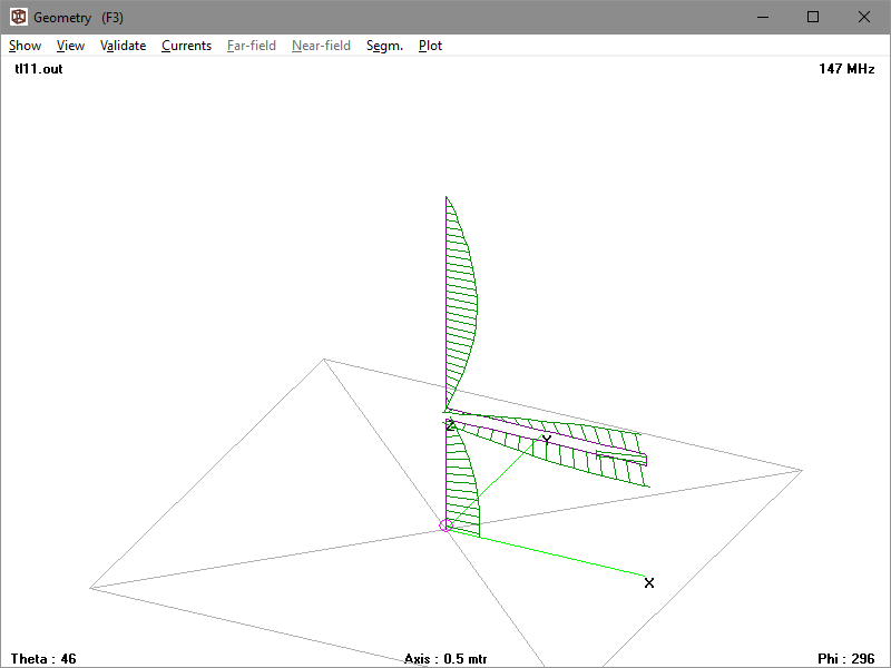
The issues discussed here are common in the ham world explanation of VSWR and analysing them provides a learning opportunity. The video contains the issues mentioned below… and some.

Right up front, eager readers are given a take home message. If something prevents them finishing the article they have learned something they can repeat as pros. So satisfying!

In order to obtain the maximum power transfer from the source to the transmission line, or the transmission line to the load, be it a resistor, an input to another system, or an antenna, the impedance levels must match.

In other words for a 50Ω system the source or signal generator must have a source impedance of 50Ω, the transmission line must be 50Ω and so must the load

Ok, it states clearly and unequivocally that a necessary condition for maximum power transfer it that source must match line and line must match load.

We will test that proposition, but firstly the detailed explanation follows… Continue reading When simple explanations target a simple audience

Single turn coaxial loop resonator analysis

Recent discussion online of a purported commercial HF small transmitting loop (STL) was challenged in analysing the structure, questioning whether such a connection was ‘correct’.

The STL used a main loop resonator and a separate small auxiliary loop for the 50Ω feed, a very common arrangement.

The main loop is a coaxial cable with, in this case, a tuning capacitor inserted between the inner conductors at each end. Above is a diagram of the main loop. Continue reading Single turn coaxial loop resonator analysis

AIM 914 produces internally inconsistent results


AIMuhf

A new release, AIM914 appeared recently.

In the common theme of one step forward, two steps backwards, this version has defects that were not present in AIM910B.

Let’s review the internal consistency of this part of the display screen.

Most of the values given above are calculated from a single measurement value, and should be internally consistent. That measurement value is translated to different quantities, many based on the stated Zref (75Ω in this case). Continue reading AIM 914 produces internally inconsistent results