AIM 916 produces internally inconsistent results


AIMuhf

AIM915a was recently pulled from the distribution site and replaced by a new release, AIM916.

AIM916 chokes on some calibration files created with earlier versions, so again historical scan data is rendered worthless. Note the illogical diagnostic message… typical AIM quality.

I cannot recall ever finding a new release that did not have significant defects, commonly inconsistency between displayed values. In the common theme of one step forward, two steps backwards, this version has defects that were not present in AIM910B.

This problem existed in AIM915a, it persists in AIM916.

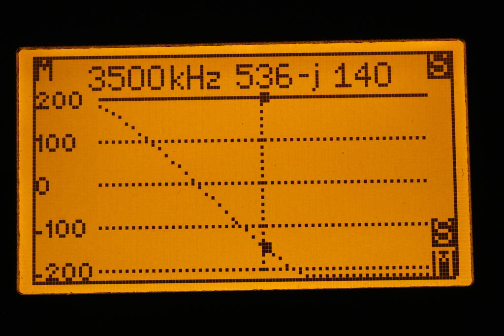
Let’s review the internal consistency of this part of the display screen.

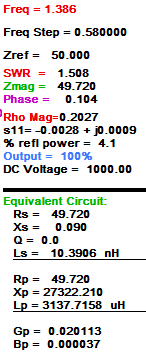
Most of the values given above are calculated from a single measurement value, and should be internally consistent. That measurement value is translated to different quantities, many based on the stated Zref (50Ω in this case). Continue reading AIM 916 produces internally inconsistent results

Radcom Feb 2019 “cable balun” – a deeper look

This article is a continuing discussion of Radcom Feb 2019 “cable balun”.

The article Baluns in antenna systems explores some different dipole and feed line configurations and the effectiveness of common mode chokes at various locations on the feed line.

Models 1, 2 and 3 particularly show the effect of a quarter wave vertical common mode conductor grounded and isolated, and a half wave vertical common mode conductor grounded.

These illustrate that those common mode conductors can be viewed to some extent as a ‘single wire’ transmission line, and the impedance presented at the dipole feed point is low or high in keeping with simple transmission line analysis of a shorted or open line of quarter or half wave length.

The question then arises with the Radcom “cable balun”, does it behave similarly, to what extent does the folding of the conductor affect its quarter wave resonance.

NEC models

One way to explore this is to construct an NEC model of the structure and a reflection of itself.

Three quarter wavelength a side folded

Above is the serpentine structure of three quarter wavelength folded, and below it, a reflection of itself. The whole structure is fed in the middle and the impedance vs frequency charted. Continue reading Radcom Feb 2019 “cable balun” – a deeper look

Designing a Gamma Match – confirmation of as-built antennas

Much is written about the virtue of the Gamma Match, and near as much about how they work, and the difficulty in design and implementation.

Designing a Gamma match using a Smith chart showed a design method for a simple Gamma Match using a Smith chart as the design tool.

This article visits the implementation on a pair of antennas that I built 50 years ago, and are still in use today (albeit with some small preventative maintenance once during that interval). The basic antenna is a four element Yagi for 144MHz copied from an ARRL handbook of the time, probably based on NBS 688. It was designed to deliver a split dipole feed point impedance of 50+j0Ω.

I built them using a Gamma Match, partly to get some familiarity, but mostly to implement a Gamma Match that was reliable, weatherproof and lasting… features that are alien to most implementations I had seen at that point.

Both antennas were constructed and the Gamma Match adjusted for VSWR<1.1 using a Bird 43 directional wattmeter. The dimensions of each (including the key gamma dimensions) are the same, not surprising, but a confirmation of repeatability. See Novel Gamma Match Construction for more discussion.

Above is a dimensioned drawing of the construction. Continue reading Designing a Gamma Match – confirmation of as-built antennas

Radcom Feb 2019 “cable balun”

A correspondent asked for an explanation of a novel balun described in Radcom Feb 2019 by K3MT.

Above is a diagram of the so-called “cable balun”.

To evaluate it, I have inserted it into one of the NEC models used for the article Baluns in antenna systems, the model used for Model 3 which I will repeat here for convenience. Continue reading Radcom Feb 2019 “cable balun”

Elecraft CP-1 directional coupler – magnetics review

Elecraft produces a directional coupler that may interest QRP aficionados. It comes with instructions for 20dB and 30dB coupling factors rated at 25 and 250W respectively from 1 to 30MHz.

This article reviews the magnetics design of the -20dB / 25W coupler.

The coupler uses a type of Sontheimer coupler (Sontheimer 1966) and these are commonly poorly designed. The first question is whether the magnetising impedance of T2 which appears in shunt with the load is sufficiently high to not give rise to poor insertion VSWR. Continue reading Elecraft CP-1 directional coupler – magnetics review

A fourth round with the FA-VA5 antenna analyser

I recently acquired a FA-VA5 antenna analyser.

Before trusting measurements made with any instrument, its behaviour should be validated, and this article documents issues discovered in one thread of tests. The developer does not like the term “defects”, he prefers “issues”, a soft denial of “problems”.

So, the test scenario is the VA5 measuring the impedance looking into a 35m length of RG6 coax with an open circuit at the far end. The VA5 has been SOL calibrated with the higher quality loads sold by SDR-kits, and the test is a 3.5MHz. The firmware is the latest, v1.08 (about 3 months old).

The screenshots are taken with a camera, there does not seem to be a method of uploading screenshots to a PC.

Above is a swept Z measurement just above the half wave resonance of the line section. The impedance at the marker is comparable with that measured using an AA-600, so I would accept that it is probably correct. The graph is another matter. Continue reading A fourth round with the FA-VA5 antenna analyser

A third test of the FA-VA5 antenna analyser

I recently acquired a FA-VA5 antenna analyser.

Whilst preparing A first test of the FA-VA5 antenna analyser, issues were noticed with the user interface design / implementation. I stated in a later article that The matter of the clumsy / unproductive user interface will be explored more at a later time.

This article introduces a short video demonstration of the frustrating / unreliable user interface (UI) in firmware v1.08 where buttons do not seem to operate intuitively and consistently.

The video shows that whilst the up down buttons seem to work reliably and consistently in ‘menu’ mode, they do not do so when trying to adjust the frequency. Continue reading A third test of the FA-VA5 antenna analyser

Should you trust your VSWR meter – linearisation

Should you trust your VSWR meter? asked an interesting question, and Should you trust your VSWR meter – detector linearity discussed a problem apparent in may VSWR meters.

This article illustrates one method of linearisation of the detector response of a practical VSWR meter.

Radio-kits SWR meter

This article contains an analysis of the analogue circuitry of the Radio-kits SWR meter.

The directional coupler at top left contains half wave peak detectors for forward and reflected waves. They are wired to the two compensated op amps at lower right (the connections are not shown on the circuit as the coupler may be remote, follow the terminal designations). Continue reading Should you trust your VSWR meter – linearisation

Should you trust your VSWR meter – detector linearity

Should you trust your VSWR meter? asked an interesting question, and based on experience, including a relevant example, concluded:

The answer is no, like any measurement instrument, prove that it is trustworthy in the intended application.

It went on to ask:

If the VSWR meter is designed to fail, why does it fail?

This article contains an analysis of the analogue circuitry of the IC-7300 directional coupler to explain the likely cause of its poor behaviour.

IC-7300 directional coupler schematic


Above is an extract of the IC-7300 circuit in the area of the directional power coupler used for VSWR measurement. The circuit is a quite conventional Bruene coupler, and its response is similar to several types of directional couplers that produce a DC output voltage from a half wave detector. Continue reading Should you trust your VSWR meter – detector linearity

Should you trust your VSWR meter?

One often sees newbies ask about their VSWR meter readings, and a common observation is that the measured VSWR is better at low power and as power is increased, VSWR increases.

With the evolution of the ‘shack in a box’, and knowledge and experience to match, the problem is often reported observed with the transceiver’s internal VSWR meter.

Some of these ‘shack in a box’ have some pretty nifty features, for example the very popular Icom IC-7300 not only has an internal VSWR meter for the HF bands, but it can perform an assisted sweep and display the results graphically.

Isn’t that a great idea, so convenient, all good!

Or is it? Continue reading Should you trust your VSWR meter?