Calculate Loss from s11 and s21 – convenient online calculator

I often need to calculate loss from marker values on a VNA screen, or extracted from a saved .s2p file.

Firstly, loss means PowerIn/PowerOut, and can be expressed in dB as 10log(PowerIn/PowerOut). For a passive network, loss is always greater than unity or +ve in dB.

\(loss=\frac{PowerIn}{PowerOut}\\\)

Some might also refer to this as Transmission Loss to avoid doubt, but it is the fundamental meaning of loss which might be further qualified.

So, lets find the two quantities in the right hand side using ‘powerwaves’ as used in S parameter measurement.

s11 and s21 are complex quantities, both relative to port 1 forward power, so we can use them to calculate relative PowerIn and relative PowerOut, and from that PowerIn/PowerOut.

PowerIn

PowerIn is port 1 forward power less the reflected power at port 1, \(PowerIn=P_{fwd} \cdot (1-|s11|^2)\).

PowerOut

PowerOut is port 2 forward power times less the reflected power at the load (which we take to be zero as under this test it is a good 50Ω termination), \(PowerOut=P_{fwd} \cdot |s21|^2 \).

Loss

So, we can calculate \(loss=\frac{PowerIn}{PowerOut}=\frac{\frac{PowerIn}{P_{fwd}}}{ \frac{PowerOut}{P_{fwd}}}=\frac{1-|s11|^2}{|s21|^2}\)
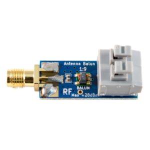
Noelec makes a small transformer, the Balun One Nine, pictured above and they offer a set of |s11| and |s12| curves in a back to back test. (Note: back to back tests are not a very reliable test.) Continue reading Calculate Loss from s11 and s21 – convenient online calculator
Measure transmission line Zo – nanoVNA – PVC speaker twin

There are many ways to get a good estimate of the characteristic impedance Zo of a transmission line.

One method is to measure the input impedances of a section of line with both a short circuit and open circuit termination. From Zsc and Zoc we can calculate the Zo, and the complex propagation constant \(\gamma=\alpha + \jmath \beta\), and from that, MLL.

Calculation of Zo is quite straightforward.

The solution for γ involves the log of a complex number \(r \angle \theta\) which is one of the many possible values \(ln(r) + j \left(\theta + 2 \pi k \right)\) for +ve integer k. Conveniently, the real part α is simply \(ln(r) \). The real part of γ is the attenuation in Np/m which can be scaled to dB/m, and the imaginary part is the phase velocity in c/m. The challenge is finding k.

Measurement with nanoVNA

So, let’s measure a sample of 14×0.14, 0.22mm^2, 0.5mm dia PVC insulated small speaker twin.

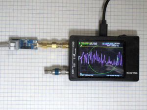
Above is the nanoVNA setup for measurement. Continue reading Measure transmission line Zo – nanoVNA – PVC speaker twin

Measure transmission line Zo – nanoVNA – CCS RG6

There are many ways to get a good estimate of the characteristic impedance Zo of a transmission line.

One method is to measure the input impedances of a section of line with both a short circuit and open circuit termination. From Zsc and Zoc we can calculate the Zo, and the complex propagation constant \(\gamma=\alpha + \jmath \beta\), and from that, MLL.

Calculation of Zo is quite straightforward.

The solution for γ involves the log of a complex number \(r \angle \theta\) which is one of the many possible values \(ln(r) + j \left(\theta + 2 \pi k \right)\) for +ve integer k. Conveniently, the real part α is simply \(ln(r) \). The real part of γ is the attenuation in Np/m which can be scaled to dB/m, and the imaginary part is the phase velocity in c/m. The challenge is finding k.

Let’s take an example from recent measurements of 35m of CCS RG6 coax, and extract the s11 values recorded in saved .s1p files @ 1.87MHz. The saved data in MA format, magnitude and angle (in degrees).

Calculate Zo and gamma is flexible and can accept the MA format data directly.

Above, the results. Zo is 74.73-j1.156Ω, and matched line loss MLL is 0.03281dB/m. This MLL is quite a deal higher than you might find in many line loss calculators, they often fail on CCS cables. Continue reading Measure transmission line Zo – nanoVNA – CCS RG6

Nichols: The Two Bird Experiment

With the following introduction, (Nichols nd) tries to demonstrate some important principles. He says…

This really tests your understanding of transmission line theory.

Above is Nichols’ test setup, simple enough.

With the transmitter keyed, the transmatch is adjusted to show zero reflected power on Bird Wattmeter #1. Transmitter is then adjusted to generate exactly 100 watts of forward power indicated on Bird Wattmeter #1. Bird directional Wattmeter #2 indicates about 36 watts of REFLECTED power. (Charts are readily available to show that a 4:1 mismatch gives about 36% reflected power).

Continue reading Nichols: The Two Bird Experiment

Conductors for a Guanella 1:1 balun – discussion

This article discusses some design factors that should be considered when designing / implementing a Guanella 1:1 balun (often known as a common mode choke).

The behavior of a Guanella 1:1 balun can conveniently be separated into its concurrent common and differential modes.

It is the differential mode that is of most interest when it comes to conductors. Continue reading Conductors for a Guanella 1:1 balun – discussion

The requisite knowledge does not come in the box

Every so often, I see a post in an online forum setting out a problem along the lines of:

I just put my brand new dool-band vertical up with 100′ of fitted Super400, and connected my brand new analyser and selected measure coax loss and it says my coax loss it 9.2dB. I gotta pull this crap Super400 down and return it to the shop, would someone recommend good coax to me?

Continue reading The requisite knowledge does not come in the box

nanoVNA – touch screen problems

My nanoVNA-H v3.3 is just over six months old. It has succumbed to most of the common hardware faults and some of the less common ones, but until now the touch screen has worked ok.

That has changed, the bezel bears on the touch screen and causes input when the case is held even very lightly by the edges… sufficiently so that it was unusable.

A perhaps temporary resolution was to place four 1mm thick M2 5mm OD nylon washers on the front part of the case before carefully placing the PCB assembly on top, then the case back and screws. This is a bit tedious if one of the washers moves, next time it is apart to fix hardware issues, I might put a dot of CA adhesive under each washer.

The case design is inadequate, it needed some features incorporated into the molding of the front to space the edges of the bezel off the PCB so that it maintained the requisite spacing even when held, even after the molding changes over time (perhaps normalisation of stresses from the molding process).