This article explores the design / analysis of a passive receive only antenna, a K9AY loop, for the 160m band (1.8MHz).
The example and calculations assume linear systems, if there is significant nonlinearity that gives rise to significant IMD, IMD noise is not captured by the analysis.
Results are for the scenarios calculated and may not be extensible to different scenarios.
Another caveat: I have reservations about transmission line modelling in SimNEC, especially for composite conductors, but for the purposes of the discussion, assume that it is reasonably correct.
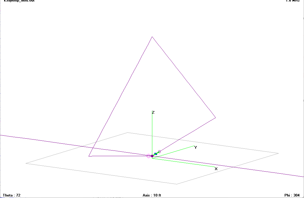
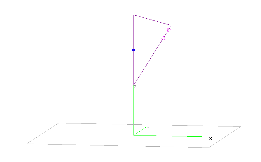
Above is the K9AY loop from a model by W7EL.
Design objective
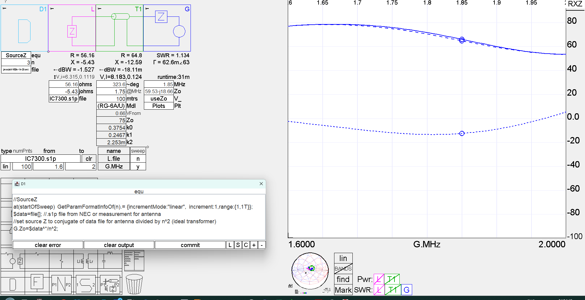
The objective here is to design a receive only antenna system that can be relatively remote from local noise sources (like house wiring), and captures enough external signal and noise that the receiver internal noise does not degrade S/N too much. Continue reading Receive only antenna for 160m – K9AY matching and performance discussion