(Varney 1958) described his G5RV antenna in two forms, one with tuned feeders and the more popular form with hybrid feed consisting of a matching section of open wire line and then an arbitrary length of lower Zo coax or twin to the transmitter.
(Duffy 2005) showed that the hybrid feed is susceptible to high losses in the low Zo line as it is often longish, is relatively high loss line and operates with standing waves.
Lets look at measurement of a real antenna, broadly typical of the G5RV. The antenna measured is a G5RV rigged in Inverted V form, 11m height at the apex and around 8m at the ends. The feed line is 2mm diameter copper spaced 50mm with occasional plastic insulators.
To some extent, the measurements are dependent on the environment, and whilst there will be variation from one implementation to another, the measurements provide a basis for exposing the configuration challenge.

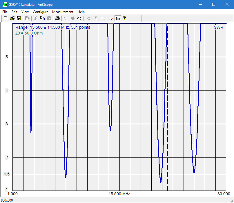
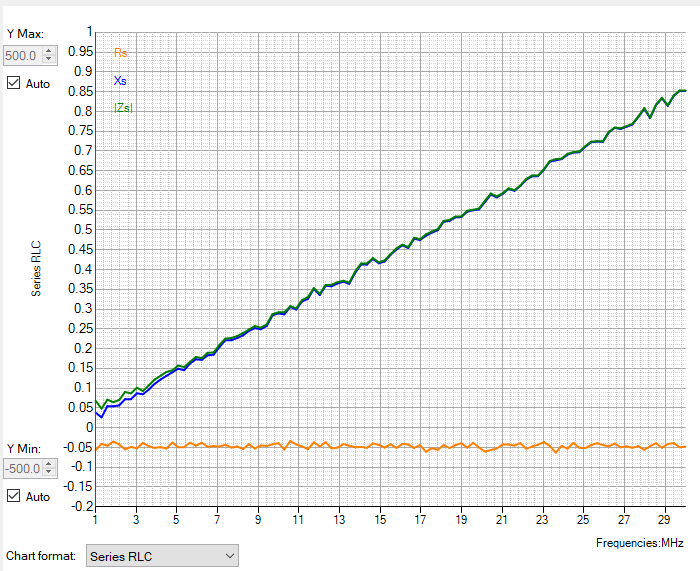
Above is a plot of VSWR50 essentially at the lower end of the matching section and low Zo line. The measurement is made looking into 0.5m of RG142 and a Guanella current balun that uses about 1m of 110Ω pair, it is essentially the load end VSWR of a hybrid feed were it used. Continue reading The quarter sized G5RV with hybrid feed
Last update: 21st February, 2021, 6:41 AM