Expected ambient noise – in practice

This posts shows a measurement of ambient noise and comparison with the data given at Expected ambient noise and its more detailed references.

The test scenario is my 40m station, a G5RV inverted V dipole with tuned feeders, a balun and ATR-30 ATU. Antenna system losses are less than 1dB.

Clip 200

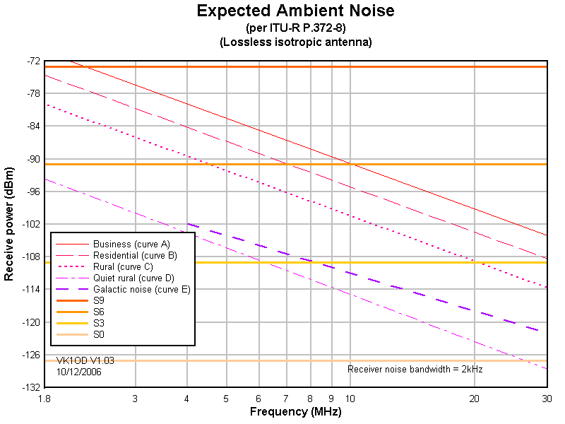
The chart above gives a range for expected ambient noise at 40m.

40mAmbientNoise

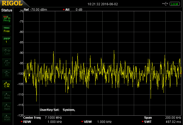
Above is a screen shot from a spectrum analyser measuring power in 1kHz bandwidth from 7.0 to 7.1MHz. The band is mostly unoccupied, and the mean noise power is about -99dBm, it would be 3dB higher in 2KHz bandwidth (ie -96dBm). Continue reading Expected ambient noise – in practice

Expected ambient noise

One of the casualties of the cessation of VK1OD.net was an article on expected ambient noise.

Clip 200

The original work was based on ITU-R P.372-8 which has been updated to -10, -12 and now -13, but the updates do not alter the basis for the original article.

Since the work was a reference cited on my FSM pages, it has been updated and copied to Expected ambient noise level. The graphics and tables in the article and the PDF file all refer to ITU-R P.372-8 but remain correct wrt ITU-R P.372-13 (2016).

PAROT with transformerless power supply and 10A SSR

This article documents an implementation of PAROT (Power Amplifier Run On Timer) using Transformerless power supply for PAROT.

This PAROT uses a 10A SSR for 230V mains switching and does not include PTT switching, but space exists for a FOD852 opto coupler for PTT switching.

The immediate application is to control my main station power supply so that if it has been in use, is hot and fans are running, the PAROT provides in this instance a 5min cool down before powering down.

Parot100Above is the electronics built on a small piece of Veroboard.

Parot101Above is the copper side of the Veroboard. The layout is designed to accomodate another implementation using a small Triac to switch a 230V AC relay. The board has been given a heavy coat of acrylic PCB lacquer to improve voltage withstand.

The PAROT is assembled inside a small die cast aluminium box with stick-on rubber feet.

Parot102Above is a view of the interior of the box. A 430V MOV is connected across the SSR output terminals, it is not clear whether the device has internal protection (Chinese product, very brief data). The LED / momentary switch on the right is the only control and indicator for PAROT operation. Note that because of the transformerless power supply, everything inside the box is potentially at mains voltage… a fact that must be kept in mind when working on it. An isolation transformer is a worthwhile tool for working on these type of things. Continue reading PAROT with transformerless power supply and 10A SSR

Arduino app to set DS1307 Real Time Clocks

I use a number of implementations of the DS1307 or DS3231 Real Time Clock chip, preferably the latter these days as they are considerably more accurate and compatible with DS1307 code.

In some applications, it is necessary or sometimes just better to preset the clock before connecting it into the application, and the need arises to set the clock ‘stand alone’. The method I have used for this has been clumsy and not as accurate as one might want for the DS3231, so this article describes a new solution.

IMG_1563

The solution uses an Arduino as the engine if you like. Above is an Arduino Pro, but a range of similar Arduinos would be equally suitable. ALso pictured are three RTCs, one connected to pins A2, A3, A4 and A5 providing GND, VCC, SDA and CLK respectively. Continue reading Arduino app to set DS1307 Real Time Clocks

Transformerless power supply for PAROT

This article documents design of a capacitive transformerless power supply for operating low voltage, low power logic from power mains. The intended application is PAROT (Duffy 2013), though it has potentially wider application.

(Microchip 2004) gives a method for design of a capacitive transformerless power supply for operating low voltage, low power logic from power mains. The equations seem simplistic for a circuit whose apparent simplicity belies the complexity of an optimal design that properly tolerates supply voltage and load variations. For that reason, a SPICE simulation was used to refine a design.

The immediate application is for the PAROT chip driving a 40A SSR.

Clip 197

Above is measured characteristic of a Fotek 40A SSR, it seems typical of several similar types on hand. It appears that much smaller SSRs in the 2A range require fairly similar current. Continue reading Transformerless power supply for PAROT

Fox flasher MkII – high power 2 LED solar powered beacon

Fox flasher MkII – owenduffy.net described an animal deterrent based on an STC 8051 microcontroller and running from a single LiPo cell.

This article describes a further development using a solar cell, shunt regulator, 1S LiPo cell with protection board, and two high power red LEDs.

FF100Above, the unit constructed in a medium size Jiffy box, and a 6V 0.6W PV panel fixed to the top with silicone adhesive. The LDR is fixed to one end with silicone adhesive.

Two SM 1W red LEDs are fitted to opposite sides. They are 120° LEDs, the holes are countersunk to provide for light dispersion and the LEDs clamped to the inside with small brass brackets and heat sink rubber, a little silicone adhesive seals the holes. Continue reading Fox flasher MkII – high power 2 LED solar powered beacon

Field strength survey of an M40-1 short helical vertical on 40m

This article documents a field strength survey of an M40-1 short helical vertical on 40m.

This test is more a feasibility study of the experimental method and apparatus than an absolute measure of the antenna.

The antenna under test is described at AUT – MobileOne M40-1 40m helical.

Field strength was measured using a small square untuned loop and VK3AQZ RF power meter (RFPM1), and data was captured using A prototype data logger for RFPM1.

Power meter

VK3AQZ RF power meter (RFPM1) described my build and calibration  of the RFPM1.

RFPM00Above is the RFPM1, shown with two probes, but only one probe is required for this procedure, the other is disconnected. The RFPM1 directly reads input power in dBm.

Loop antenna

Clip 071

The loop antenna used was described at (Duffy 2007). It is a small square loop (600mm sides) fed in one corner with a 1:1 voltage balun. Continue reading Field strength survey of an M40-1 short helical vertical on 40m

USB-A to DC 5.5/2.1mm power cable – current carrying capacity

The growing popularity of 5V plug packs and Li-ion power banks with USB A connectors provides a convenient source of power for some projects, and a USB-A to 5.5/2.1mm DC cable is a possible connection option.

Scouring eBay turned up some sources, but one can never assess the quality of the things because usually there are no meaningful specification offered, and lets face it, they are Chinese.

USB-21

Above are two sample 1m cables that I purchased, the left one for about A$1, and the right for about A$3.50 (posted).

Loop resistance of the cables was measured with Kelvin probes to assess their current carrying capacity from a voltage drop perspective.

DC loop resistance of the one on the right was 0.16Ω, so the maximum current for a 5% voltage drop is 5*0.05/0.16=1.6A… not quite a 2A rating.

DC loop resistance of the one on the left was 3.3Ω, so the maximum current for a 5% voltage drop is 5*0.05/3.3=0.075A… not even a 100mA rating.

This is not surprising, experience with USB-A to USB-micro cables has revealed similar variation, and an explanation why so many of these cables are hopeless in battery charging applications.

Making sense of LED output figures

Browsing eBay for some high power LEDs for a current project created frustration in trying to wade through the stated performance figures (to they extent that they can be relied upon).

LEDs are often headlined as having some luminous intensity in candelas, but while that might seem to be a good measure of the ‘brightness’ of the LED viewed on-axis, it gives no information about the spatial distribution off-axis and the total luminous flux output or flux density.

I wrote a little online calculator that can be of assistance in finding the total luminous flux and flux density give luminous intensity and apex angle, Calculate luminous flux (lm) from luminous intensity (cd) and apex angle (°). (Note that specified luminous intensity is usually on axis and should be discounted by perhaps 20% to provide an average luminous intensity over the cone angle.)

Example 1

An example, an eBay seller advertises:

Specifications:
Source Material: InGaN !
Emitting Colour: 0.5W 10MM HI POWER White 0.5W LED
LENS Type: Water clear
Luminous Intensity-MCD: Typ: 290,000 mcd
Reverse Voltage: 5.0 V
DC Forward Voltage: 3.2 ~ 3.4V
DC Forward Current: 100mA
Viewing Angle: 40 degree
Lead Soldering Temp: 260¡ãC for 5 seconds
Power Dissipation: 500mW

Does it appear rational? Lets calculate average luminous intensity at 80% of 290cd, 232cd. Lets assume the viewing angle is the half power beamwidth.

Screenshot - 15_04_16 , 09_50_50

Above is a calculation from the specifications. Of concern is the calculated luminous efficiency of 266lm/W, it is perhaps three times or more the expected value, so it questions the accuracy of the claims. Even at 0.5W input, the luminous efficiency is unrealistically high. Continue reading Making sense of LED output figures