nanoVNA-H – woolly thinking on MLL measurement

There is little doubt that the nanoVNA has made VNAs very popular in the ham community, possibly more so that any other device.

Eager owners are trying to apply them to solve lots of problems, often without sufficient knowledge or experience to properly inform the measurements.

An example that has a appeared a few times on online forums in the last weeks is measuring the matched line loss (MLL) of a section of RG6 coax… to inform a decision to discard it or keep it.

The common approach is to use a measurement of |s11| and to calculate Return Loss and infer the MLL.
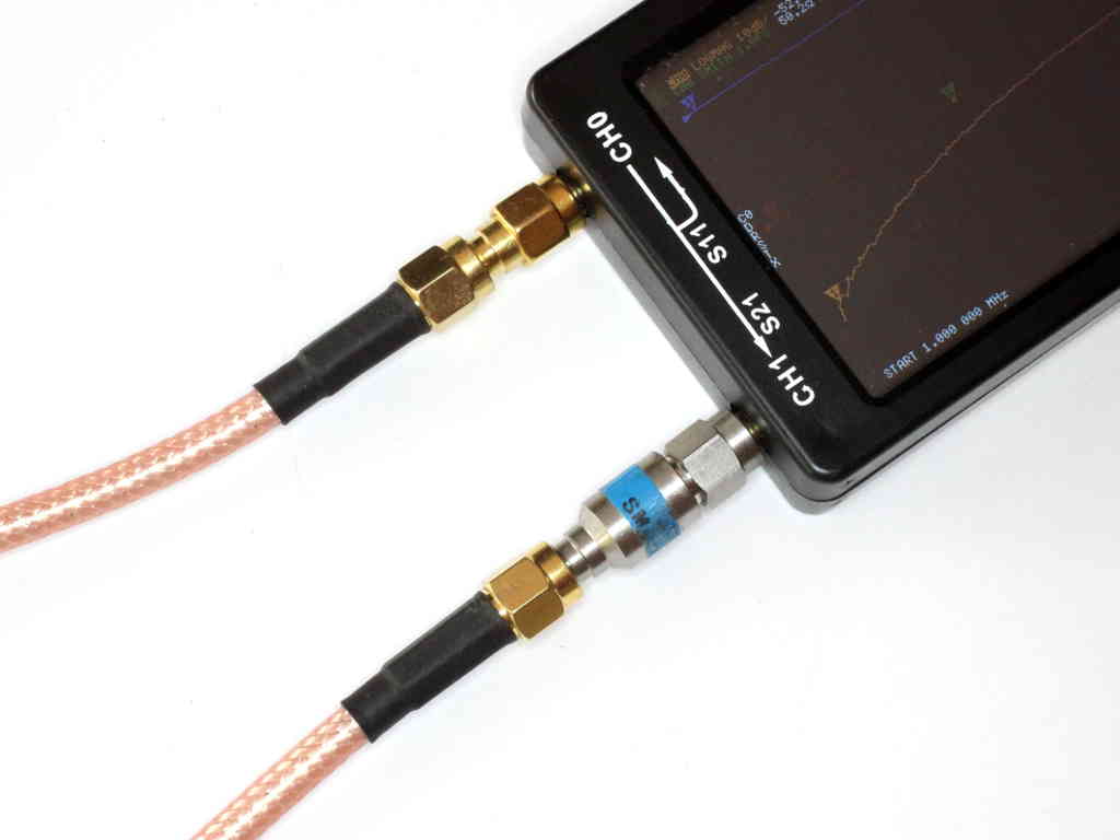
DUT

For discussion, lets consider an example of 30′ of Belden 1694A RG6 solved in Simsmith. We should note that unlike most RG6 in the market today, this uses a solid copper centre conductor.

Short circuit termination

Some authors insist that the half return loss method is to be performed using a short circuit test section. Bird does this in their Bird 43 manual.

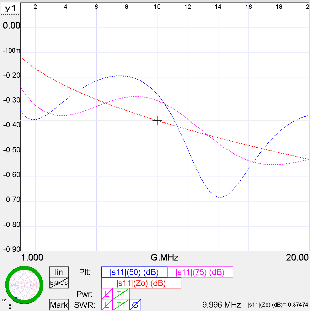
Above is a plot of calculated |s11| (-ReturnLoss) from 1 to 20MHz for the test section. The three plots are of |s11| wrt 50Ω, 75Ω and frequency dependent actual Zo (as calculated for the model). The cursor shows that the actual |s11| is -0.37474dB (ReturnLoss=0.37474dB). Using the half return loss method MLL=ReturnLoss/2=0.37474=0.187dB/m. Continue reading nanoVNA-H – woolly thinking on MLL measurement

nanoVNA-H – thinking laterally

A question was asked in an online forum specific to nanoVNA as to how the use the nanoVNA to check the attenuation loss in some old & weathered RG-6 (75 ohm) cables for the TV signal frequencies. Excuse the term attenuation loss, lets assume the poster is asking for matched line loss (MLL).

The assembled experts are offering solutions to transform the ports to 75Ω and make a measurement, deducting the loss of the transformation (minimum loss pads were suggested).

There is a very simple solution that should be quite practical for the scenario described. Let’s work through two examples using 35.5m of unbranded quad shield RG6 with CCS centre conductor (of unknown quality) for the DUT. Continue reading nanoVNA-H – thinking laterally

nanoVNA-H – de-embedding the feed line in remote measurement

There are often times when it would be useful to transform measurements made looking into a feed line to the other end of the feed line.

Ham lore

Common advice given by online ham experts include:

  1. it just cannot be done, the best (only) point to measure an antenna is at the feed point;
  2. it can be done, but only with an integral number of half waves of feed line;
  3. use the port extension facility in your software;
  4. use software package x;
  5. do an OSL cal with the feed line being part of the fixture.

Continue reading nanoVNA-H – de-embedding the feed line in remote measurement

nanoVNA-H – Port 2 attenuator for improved Return Loss

nanoVNA-H – measure 40m low pass filter for WSPRlite flex describes measurement of the response of a filter.

The filter is of a type that depends on its source and termination impedance for as designed performance.

The article mentioned the use of a 10dB attenuator on the nanovna-h Port 2 for the purpose of improving the accuracy of the load impedance for the filter.

Like most low end vnas, the nanoVNA Port 2 VSWR or Return Loss is not wonderful, not as good as needed for some types of measurement. Return Loss can be improved by placing an attenuator ahead of the port. The nanoVNA-H v3.3 already includes an attenuator on the PCB, and the nanovha-H v3.4 increased that attenuation by about 5dB to improve Return Loss by about 10dB.

In my own case, I am using a nanoVNA-H and upon measurement of |s11| (-ReturnLoss) I determined that it needed to be improved by 20dB for my use so I purchased and installed a 10dB attenuator semi permanently on the Port 2 connector.

Above, the 10dB attenuator is semi permanently attached to Port 2 and also serves the purpose of a connector saver. There is a connector saver semi permanently attached to Port 1. Continue reading nanoVNA-H – Port 2 attenuator for improved Return Loss

A common mode choke for a VDSL pair – LF1260 core

This article describes a common mode choke intended to reduce RF interference with a VDSL service.

The MDF is located where the underground cable enters the building. From here it rises vertically and travels some 25m across the ceiling to the VDSL modem. Continue reading A common mode choke for a VDSL pair – LF1260 core

nanoVNA-H – measuring an inductor – is it a no-brainer?

Let’s explore measurement of a test inductor with the nanovna.

Above is the test inductor, enamelled wire on an acrylic tube.

An online expert’s advice make this task look like a no-brainer:

For a 100 nH inductor you are probably using an air wound coil so you won’t see that much change in inductance with frequency. However, inductors made with toroids will because the permeability of the core goes down with frequency.

So, this is an air cored inductor, permeability is approximately that of free space, a constant 4πe-7 independent of frequency. Nevertheless we will see that apparent inductance can change with frequency. Continue reading nanoVNA-H – measuring an inductor – is it a no-brainer?

nanoVNA-H – continuing USB-C repair

I have reported issue with the USB-C plug / socket arrangement on the nanoVNA-H.

It is very sensitive to any jiggling of the cable or connector, causing a reset of the nanoVNA which almost always means lost work. The supplied cable was a partial cause, but sadly the jack on the PCB is also faulty.

This has progressively gotten worse to the point the nanoVNA-H is unusable. I have had a replacement socket on order for months from China where public health problems are causing chaos, it has only just shipped so could be some months yet.

I do realise that this is replacing cheap Chinese junk with cheap Chinese junk.

Anyway… it finally arrived after many months. A pack of 10 sockets cost $2.30 incl shipping, so it gives one a fair idea of how cheap the low grade connector that was used would have come.

Above, the replacement USB-C socket soldered in to the board without removing the display. The SB1 pad lifted of the board during removal of the old socket, no connection is made to it, so no harm done. Continue reading nanoVNA-H – continuing USB-C repair

Current regulation dynamics of Atten APS3005S

This article documents a simple test to ascertain whether the current regulation dynamics of are good enough to use for testing strings of LEDs as found in much modern lighting

Atten-hcctl00

The APS3005S is a linear bench top power supply 0-30VDC at 0-5A with adjustable voltage and current regulation… so called constant voltage and constant current modes.

A pair of 900mm long small gauge (0.5mm^2) hook up leads were used to apply a short circuit to the power supply, and current was set to 0.1A. The resistance and inductance of these leads will to some extent limit the peak current.

The short circuit was removed and the power supply set to 30V out.

The short was reapplied and the current captured with a current probe. The current probe calibration is 1mV/10mA.

Above, the peak current is 6680*0.1=66.8A, that is 668 times the set value. Continue reading Current regulation dynamics of Atten APS3005S

nanoVNA-H – continuing USB-C woes #2

I have reported issue with the USB-C plug / socket arrangement on the nanoVNA-H.

It is very sensitive to any jiggling of the cable or connector, causing a reset of the nanoVNA which almost always means lost work. The supplied cable was a partial cause, but sadly the jack on the PCB is also faulty.

This has progressively gotten worse to the point the nanoVNA-H is unusable. I have had a replacement socket on order for months from China where public health problems are causing chaos, it has only just shipped so could be some months yet.

I do realise that this is replacing cheap Chinese junk with cheap Chinese junk.

Replacement of the USB-C socket will be difficult, fortunately it is the 12/16 pin version rather than the full 24 pins… but I do wonder at the wisdom of using a USB-C over the proven micro USB connector.

Above, the old socket has been removed from the board. One pad came off with the socket, but it is the unused SB1 pad. Of greater concern is whether the slight movement of the some other pads might cause conductor cracking. I do see signs that a couple of pins might not have tinned the full pad area, a hint of low quality board fabrication and a possible contribution to intermittent connection.

An alternate recovery is to cut the end off a USB cable and permanently wire it directly into the board.

So for now, the nanoVNA-H awaits parts again.

nanoVNA – VSWR in terms of 400Ω

I was asked whether the nanoVNA can display VSWR in terms of 400Ω or some other arbitrary impedance.

Some antenna analysers and VNAs support display of results in terms of some specified impedance other than 50Ω, sometimes only a limited fixed set.

The direct answer to the question is “probably no, not directly on the ‘original’ nanoVNA today”, there are many firmware forks and many PC clients for nanovna, and now many significantly hardware versions appearing. Things may change.

However, if you can save a set of impedance measurements, they can be converted to VSWR relative to some other impedance reference.

An example

At Implementation of G5RV inverted V using high strength aluminium MIG wire – impedance measurements a set of impedance measurements made with a Rigexpert AA600 is presented.

A similar set of measurements could be made with a standalone nanoVNA and saved, but given that it is such a clumsy device and its USB socket has become so unreliable, I will not repeat the measurement but use the data used for the article above.

So we have a table of frequency and (R,X) measured looking into a ‘real’ 450Ω feed line, so we will calculate wrt 450Ω but we could use any reference.

Above is a plot or (R,X) looking into the feed line. Continue reading nanoVNA – VSWR in terms of 400Ω