A common scheme for narrow band match of an end fed high Z antenna

This article discusses the kind of matching network in the following figure.

A common variant shows no capacitor… but for most loads, the capacitance is essential to its operation, even if it is incidental to the inductor or as often the case, supplied by the mounting arrangement of a vertical radiator tube to the mast. Continue reading A common scheme for narrow band match of an end fed high Z antenna

Stacking two ferrite cores of different permeability for an RF inductor

One of the magic ham recipes often proposed is to stack two ferrite cores of different permeability for an RF inductor, but an explanation is rarely offered, I have not seen one.

An explanation

Starting with some basic magnetism…

The inductance of an inductor is given by \(L=N\frac{\phi}{I}\).

For a closed magnetic circuit of high permeability such as a ferrite cored toroid, the flux is almost entirely contained in the core and the relationship is \(\mathcal{F}=\phi \mathcal{R}\) where \(\mathcal{F}\) is the magnetomotive force, \(\phi\) is the flux, and \(\mathcal{R}\) is the magnetic reluctance. (Note the similarity to Ohm’s law.) Continue reading Stacking two ferrite cores of different permeability for an RF inductor

Differences in two similar simple untuned small loop configurations

A correspondent asked about the difference between two small untune loops mentioned in two of my articles, this article explains.

Firstly lets set the context, a small loop means less than λ/10 perimeter, and untuned is to mean that the loop is loaded directly, in this case by a receiver which we will assume has an input impedance of 50+j0Ω.

Let’s look at the two cases. The key difference is in the connection at the gap:

  • the first has a short circuit coaxial stub of half the perimeter between the inner conductor at the right side of the gap and the outer surface of the outer conductor at the right side of the gap; and
  • The second directly connects the inner conductor at the right side of the gap and the outer surface of the outer conductor at the right side of the gap.

Small single turn un-tuned shielded loop

Above is a diagram of the loop. Continue reading Differences in two similar simple untuned small loop configurations

Another small efficient matching transformer for an EFHW – 2643251002

This article describes a small matching transformer built and measured by Luis, CT2FZI, using a Fair-rite 2643251002.

Above is the transformer with 100pF compensation capacitor across the input, and two resistors to make up a 3300Ω load in combination with the VNA port. Continue reading Another small efficient matching transformer for an EFHW – 2643251002

Shorting winding sections of a ferrite cored EFHW transformer

A chap recently posted some advice on construction of a dual ratio transformer for EFFHW antennas, advice with an informative pic, but without measurement evidence that it works well.

Pictured is a dual UnUn. I made this for experimenting. It’s both a 49 and 64 to 1 UnUn.

The 49 to 1 tap uses the SS eye bolt for the feed through electrical connection and the SS machine screw on the top is the 64 to 1 connection. If I want to use the 49 to 1 ratio, there’s a jumper on the eye bolt that connects to the top machine screw where the antenna wire is attached. The jumper shorts out the last two turns of the UnUn. Disconnect the jumper from the top connection and now you have a 64 to 1 ratio.

Continue reading Shorting winding sections of a ferrite cored EFHW transformer

RF Power Meter 2 (RFPM2) – display update

RF Power Meter 2 is a logging RF power meter based on AD8307 and ESP8266.

The original LCD display was white on blue, but was very difficult to read at some viewing angles, so it had to go. Unfortunately I could not find more displays with that hole pattern, it seems to have been discarded for a newer hole pattern as almost everything I looked at had the same newer patter.

So, the box front needed rework, and there would be visible spare holes… so a dress escutcheon was designed in Freecad and cut on a CNC router.

The escutcheon was designed to be cut from some 3mm black acrylic sheet that was on hand, and it would cover the reworked panel. Continue reading RF Power Meter 2 (RFPM2) – display update

Small efficient matching transformer for an EFHW – a Simsmith model

This article offers a simple Simsmith model for the Small efficient matching transformer for an EFHW.

Above is the model topology. D1 is a daemon block which essentially, calculates key values for the other blocks based on exposed parameters and the named ferrite material complex permeability data file. The prototype used a Fair-rite 2643625002 (#43) core. Continue reading Small efficient matching transformer for an EFHW – a Simsmith model

A simple generic Simsmith model of a linear push-pull Class B broadband HF power amplifier

This article outlines a Simsmith model developed to explore / confirm behavior of some linear Class B push-pull HF broadband power amplifiers.

The design is for a system power output of about 80W on a 24V supply, it is a combination that should work with practical system components with good efficiency.

Above is a first step, an estimate of an initial load line for the PA. The calculator is written in valve terms, but is quite applicable to this scenario. Continue reading A simple generic Simsmith model of a linear push-pull Class B broadband HF power amplifier

Ferrite cored inductors at HF – flux, loss and saturation

I see online experts opine that small signal characteristics (eg complex permeability curves) of ferrite toroids are not valid for applications such as RF common mode choke in transmitting antennas.

Others opine that saturation is a practical design limit, and for example that Bs/2 is a safe / appropriate design target.

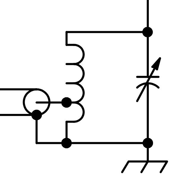
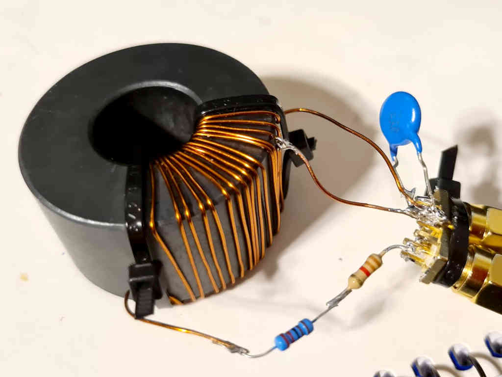
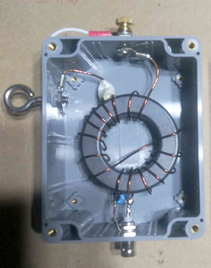
Let us consider a ferrite cored inductor at 7MHz. The inductor comprises 11t on a 11t on Fair-rite 5943003801 (FT240-43) toroid. This is a medium to high permeability ferrite material, and for that reason, has significant loss at HF. Higher and lower permeability materials are fashionable at different times, the higher permeability #31 mix is fashionable at this time.

I will work in MKS units.

Above is Fair-rite’s B-H curves for #43 material. Let’s take saturation flux density Bs to be 1500gauss or 0.15T. Continue reading Ferrite cored inductors at HF – flux, loss and saturation

EB104 alternative output circuit

One of the very important designs of HF broadband MOSFET power amplifiers was that of Helge Granberg in Motorola application note EB104.

This article offers an explanation of how the the alternative output circuit at Fig 5 of EB104 works.

Let’s look at the schematic diagram of the PA.

Above is the schematic from EB104, of interest for this article is the output circuit comprising T2 and T3 which are intended ideally to provide a drain to drain load of 50/9=5.55Ω. Continue reading EB104 alternative output circuit