Select a ferrite core material and sufficient primary turns for a low InsertionVSWR 50Ω broadband RF transformer – nanoVNA

This article demonstrates the use of a nanoVNA to select a ferrite core material and sufficient primary turns for a low InsertionVSWR 50Ω broadband RF transformer.

Simple low frequency equivalent circuit

Above is a very simple approximation of an ideal 1:1 transformer where the effects of flux leakage and conductor loss are ignored. A 1:n transformer can be modelled the same way, as if flux leakage and conductor loss are ignored, the now ideally transformed secondary load becomes 50Ω. Continue reading Select a ferrite core material and sufficient primary turns for a low InsertionVSWR 50Ω broadband RF transformer – nanoVNA

Phase of s11 and Z

Antenna system resonance and the nanoVNA contained the following:

Relationship between angle of reflection coefficient and angle of impedance

It was stated above that the angle (or phase) of s11 or Γ is not the same as the angle (or phase) of Z.

Given Zo and Γ, we can find θ, the angle of Z.

\(
Z=Z_0\frac{1+\Gamma}{1-\Gamma}\)

Zo and Γ are complex values, so we will separate them into the modulus and angle.

\(
\left | Z \right | \angle \theta =\left | Z_0 \right | \angle \psi \frac{1+\left| \Gamma \right | \angle \phi}{1-\left| \Gamma \right | \angle \phi} \\
\theta =arg \left ( \left | Z_0 \right | \angle \psi \frac{1+\left| \Gamma \right | \angle \phi}{1-\left| \Gamma \right | \angle \phi} \right )\)

We can see that the θ, the angle of Z, is not simply equal to φ, the angle of Γ, but is a function of four variables: \(\left | Z_0 \right |, \psi , \left| \Gamma \right |, \& \: \phi\) .

It is true that if ψ=0 and φ=0 that θ=0, but that does not imply a wider simple equality. This particular combination is sometimes convenient, particularly when ψ=0 as if often the case with a VNA.

This article offers a simulation of a load similar to a 7MHz half wave dipole.

The load comprises L, L1, and C1 and the phase of s11 (or Γ) and phase of Z (seen at the source G) are plotted, along with VSWR. Continue reading Phase of s11 and Z

The devil is in the detail…

An image from one of my articles has been posted online in some discussions, with attribution of the underlying image, but it includes some changes / annotations.

I think that this is a better image.

The difference is in the two pin assembly at lower centre, an addition to my original image. My recommendation is that the DUT is attached to the same side of the pin strip as was used for the calibration parts, as shown. Though I did not intend that this jig be used much above 100MHz, small details like this might improve its accuracy. Continue reading The devil is in the detail…

Improving ‘s21 shunt-through’ measurement of low impedances – more detail

Improving ‘s21 shunt-through’ measurement of low impedances canvassed a possible improvement of the s21 series-through measurement of impedance to compensate for errors in VNA port impedances that are not corrected in simpler calibration / correction schemes.

This article provides more detail on the practical test case.

A small test inductor was measured with a ‘bare’ nanoVNA SOLT calibrated, firstly using s11 reflection.

Above is the R,X,|Z| plot from the s11 reflection measurement of the unknown Zu. It shows small negative resistance, a frustration with these low end VNAs that suffer thermal drift after just a few measurements. It is less than 3min since SOLT calibration. Continue reading Improving ‘s21 shunt-through’ measurement of low impedances – more detail

Improving ‘s21 shunt-through’ measurement of low impedances

This article canvasses a possible improvement of the s21 shunt-through measurement of impedance to compensate for errors in VNA port impedances that are not corrected in simpler calibration / correction schemes.

The diagram above is from (Agilent 2009) and illustrates the configuration of a shunt-through impedance measurement. Continue reading Improving ‘s21 shunt-through’ measurement of low impedances

Antenna system resonance and the nanoVNA

With the popularity of the nanoVNA, the matter of optimisation of antenna systems comes up and the hoary chestnuts of ham radio are trotted out yet again.

Having skimmed a presentation published on the net, an interesting example is presented of an 80m half wave centre dipole with feed line and various plots from the nanoVNA used to illustrate the author’s take on things.

The author is obsessed with resonance and obsessed with phase, guiding the audience to phase as ‘the’ optimisation target. Phase of what you might ask… all the plots the author used to illustrate his point are phase of s11.

A model for discussion

I have constructed an NEC-4.2 model of a somewhat similar antenna to illustrate sound concepts. Since NEC-4.2 does not model lossy transmission lines (TL elements), we will import the feed point data into Simsmith to include transmission line loss in the model.

Above is the Simsmith model. Continue reading Antenna system resonance and the nanoVNA

Improving ‘s21 series-through’ measurement of high impedances – more detail

Improving ‘s21 series-through’ measurement of high impedances canvassed a possible improvement of the s21 series-through measurement of impedance to compensate for errors in VNA port impedances that are not corrected in simpler calibration / correction schemes.

This article provides more detail on the practical test case.

A small ferrite cored test inductor was measured with a ‘bare’ nanoVNA SOLT calibrated, firstly using s11 reflection.

Above is the R,X,|Z| plot from the s11 reflection measurement of the unknown Zu. Continue reading Improving ‘s21 series-through’ measurement of high impedances – more detail

Improving ‘s21 series-through’ measurement of high impedances

This article canvasses a possible improvement of the s21 series-through measurement of impedance to compensate for errors in VNA port impedances that are not corrected in simpler calibration / correction schemes.

The diagram above is from (Agilent 2009) and illustrates the configuration of a series-through impedance measurement. Continue reading Improving ‘s21 series-through’ measurement of high impedances

Calculate Loss from s11 and s21 – convenient online calculator

I often need to calculate loss from marker values on a VNA screen, or extracted from a saved .s2p file.

Firstly, loss means PowerIn/PowerOut, and can be expressed in dB as 10log(PowerIn/PowerOut). For a passive network, loss is always greater than unity or +ve in dB.

\(loss=\frac{PowerIn}{PowerOut}\\\)

Some might also refer to this as Transmission Loss to avoid doubt, but it is the fundamental meaning of loss which might be further qualified.

So, lets find the two quantities in the right hand side using ‘powerwaves’ as used in S parameter measurement.

s11 and s21 are complex quantities, both relative to port 1 forward power, so we can use them to calculate relative PowerIn and relative PowerOut, and from that PowerIn/PowerOut.

PowerIn

PowerIn is port 1 forward power less the reflected power at port 1, \(PowerIn=P_{fwd} \cdot (1-|s11|^2)\).

PowerOut

PowerOut is port 2 forward power times less the reflected power at the load (which we take to be zero as under this test it is a good 50Ω termination), \(PowerOut=P_{fwd} \cdot |s21|^2 \).

Loss

So, we can calculate \(loss=\frac{PowerIn}{PowerOut}=\frac{\frac{PowerIn}{P_{fwd}}}{ \frac{PowerOut}{P_{fwd}}}=\frac{1-|s11|^2}{|s21|^2}\)

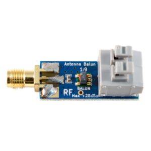
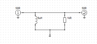
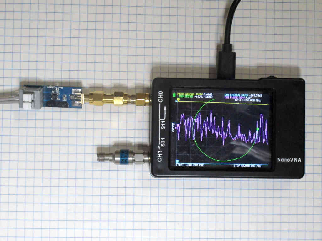
Noelec makes a small transformer, the Balun One Nine, pictured above and they offer a set of |s11| and |s12| curves in a back to back test. (Note: back to back tests are not a very reliable test.) Continue reading Calculate Loss from s11 and s21 – convenient online calculator

Measure transmission line Zo – nanoVNA – PVC speaker twin

There are many ways to get a good estimate of the characteristic impedance Zo of a transmission line.

One method is to measure the input impedances of a section of line with both a short circuit and open circuit termination. From Zsc and Zoc we can calculate the Zo, and the complex propagation constant \(\gamma=\alpha + \jmath \beta\), and from that, MLL.

Calculation of Zo is quite straightforward.

The solution for γ involves the log of a complex number \(r \angle \theta\) which is one of the many possible values \(ln(r) + j \left(\theta + 2 \pi k \right)\) for +ve integer k. Conveniently, the real part α is simply \(ln(r) \). The real part of γ is the attenuation in Np/m which can be scaled to dB/m, and the imaginary part is the phase velocity in c/m. The challenge is finding k.

Measurement with nanoVNA

So, let’s measure a sample of 14×0.14, 0.22mm^2, 0.5mm dia PVC insulated small speaker twin.

Above is the nanoVNA setup for measurement. Continue reading Measure transmission line Zo – nanoVNA – PVC speaker twin