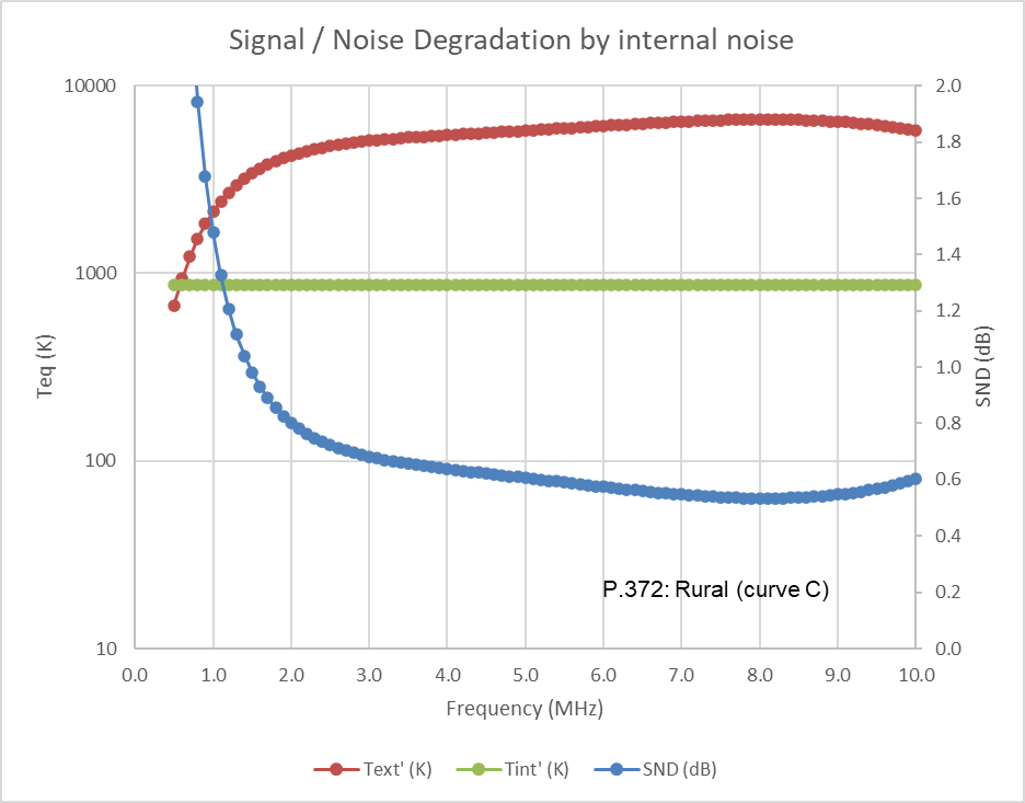
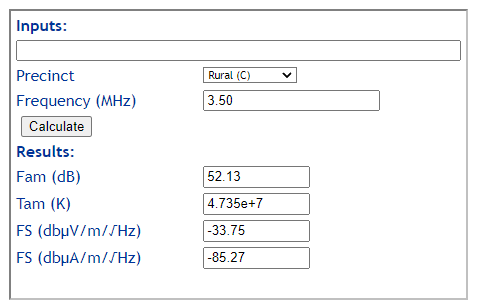
The Loop in Ground project is about a receive only antenna for low HF, but usable from MF to HF. The objective is an antenna that has low Signal to Noise Degradation (SND), and low noise pickup by virtue of some separation of near field radiators.
The antenna comprises a square loop of 3m sides of 2mm bare copper wire, buried 20mm in the soil.
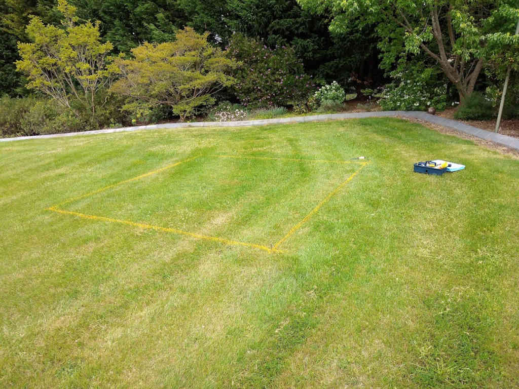
Above is the site marked out for earthworks, but excavation of a narrow slot 25mm deep. On the far side of the loop is an already installed plastic irrigation valve box for the transformer. Continue reading Loop in ground (LiG) – #10 – implementation – earthworks