MFJ-1786 loop antenna – measurements and NEC-4.2 model at 10.1MHz

My friend Carlos, VK1EA, made some measurements of an MFJ-1786 SUPER HI-Q 36″ (0.914m) DIA 10-30 MHz loop at 10.1MHz.

This article presents some modelling and analysis of the antenna principally to estimate its performance.

The loop was located at 2m above natural ground away from other conducting objects.

He tuned the loop for minimum VSWR at around 10.1MHz and took a sweep with a EU1KY antenna analyser looking through 0.5m of RG223 50Ω cable saving the results to a s1p file which was imported to Antscope.

Measurement of the real antenna

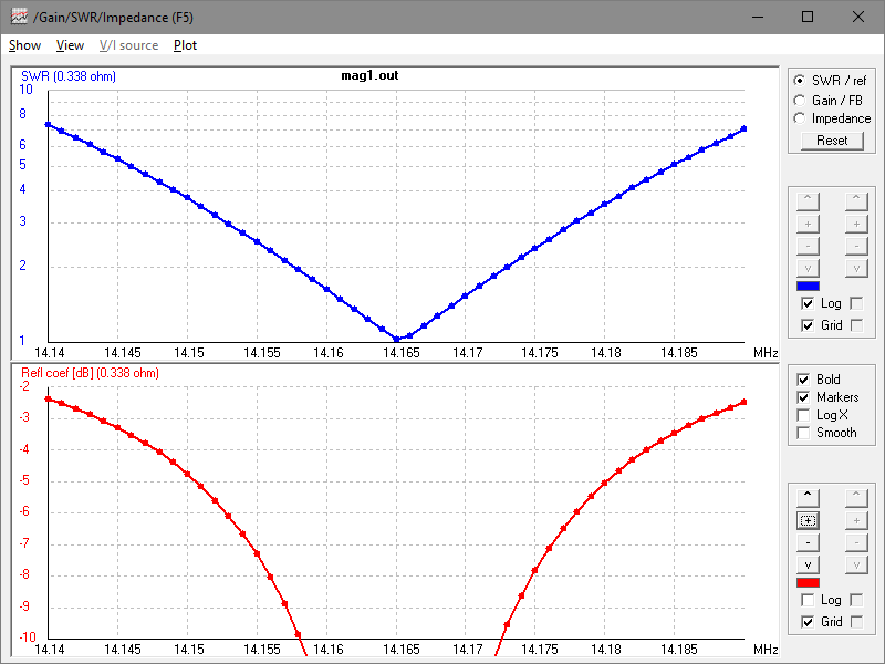
Here is the impedance plot (excuse the |Z| plot as it is Rigexpert’s concession to hams who do not understand impedance and I cannot disable it).

Above, the impedance plot. The cursor is at point of minimum VSWR, and the associated R and X values at the measurement point are not very useful. Continue reading MFJ-1786 loop antenna – measurements and NEC-4.2 model at 10.1MHz

NEC model of figure 8 transmitting loop

Variants of loops have been designed and promoted as having certain advantages, and one of those is the so-called figure 8 loop.

This article describes an NEC-4.2 model at 14MHz of an antenna similar to a commercial example.

The graphic shows the geometry. In this case the source is at the bottom of the lower loop, and the blue square is the tuning capacitor. The loop conductor is 22mm copper tube, the loop diameters are 1m, and the capacitor connection is 100mm wide. Commonly these are fed by a low loss auxiliary loop at the bottom of the lower loop, but the direct feed is quite fine for modelling the loop performance. Continue reading NEC model of figure 8 transmitting loop

W5KV’s transmitting loop measurements – DELUXE HG-1 PreciseLOOP 7MHz

W5KV documented his measurements of a 3m perimeter circular transmitting loop, DELUXE HG-1 PreciseLOOP, 2.0m centre height above ground.

This article explores his 7MHz observations.

Assuming the measurements were made with the antenna clear of disturbing conductors etc, in good condition.

Above is his VSWR scan.

The key measurements were:

  • centre frequency 7.175MHz, VSWRmin=1.1;
  • VSWR=3 bandwidth 36kHz.

Based on that, we can estimate the half power bandwidth to be 30kHz if R is less than Ro, more like 33kHz in the other case, but we will be optimists.

A NEC-4.2 model of the antenna at 14MHz was built and calibrated to the implied half power bandwidth (30kHz). Model assumptions include:

  • ‘average’ ground (σ=0.005, εr=13);
  • Q of the tuning capacitor = 2000;
  • conductivity of the loop conductor adjusted to calibrate the model half power bandwidth to measurement.

Note that the model may depart from the actual test scenario in other ways.

Above is the VSWR scan of the calibrated model, the load is matched at centre frequency and half power bandwidth is taken as the range between ReturnLoss=6.99dB points. Continue reading W5KV’s transmitting loop measurements – DELUXE HG-1 PreciseLOOP 7MHz

AE7PD’s transmitting loop measurements

AE7PD documented his measurements of a 3.16m perimeter circular transmitting loop, 1.8m centre height above ground, that he made using 16mm copper tube and a split stator tuning capacitor:

AE7PD gives the radiation efficiency on 20m as 30.5% or -5.2dB.

I present here an alternative analysis of the antenna as measured on 20m.

Assuming the measurements were made with the antenna clear of disturbing conductors etc, and that 5/8″ tube means 16mm OD.

The key measurements were:

  • centre frequency 14.165MHz, VSWRmin=1.0;
  • VSWR=2.62 bandwidth 22kHz.

A NEC-4.2 model of the antenna at 14MHz was built and calibrated to the measured half power bandwidth (22kHz). Model assumptions include:

  • ‘average’ ground (σ=0.005, εr=13);
  • Q of the tuning capacitor = 2000;
  • conductivity of the loop conductor adjusted to calibrate the model half power bandwidth to measurement.

Note that the model may depart from the actual test scenario in other ways.

Above is the VSWR scan of the calibrated model, the load is matched at centre frequency and half power bandwidth is taken as the range between ReturnLoss=6.99dB points. Continue reading AE7PD’s transmitting loop measurements

Findling & Siwiak 2012 measurements of an Alexloop – discussion

I mentioned in Findling & Siwiak 2012 measurements of an Alexloop issues with their efficiency calculation.

Above is an extract from (Findling & Siwiak 2012).

(Siwiak & Quick 2018) give an equivalent circuit of lossless loop structure in free space.

When tuned to resonance, the response is simply that of a series RLC circuit where R=Rr (the radiation resistance) which is dependent on frequency, but varies very slowly with frequency compared to the net reactance X.

Above is a NEC simulation of such a loop. Continue reading Findling & Siwiak 2012 measurements of an Alexloop – discussion

G3CWI 2018 measurements of an Alexloop Walkham

Richard, G3CWI, measured the impedance and bandwidth of a Alexloop Walkham, a popular small transmitting loop (STL). The antenna was situated in the clear at 1.65m centre height above natural ground.

The key measurements were:

  • centre frequency 7.014MHz, |Z|=51Ω, VSWR=1.1;
  • VSWR=3 bandwidth 16.2kHz.

The step size of the analyser prevented measurement exactly at resonance, but R changes very closely with frequency near resonance so we can estimate it quite well. The above figures can be used to find R close to resonance.

Within the limits of measurement error, we can say that R at resonance should be very close to 51Ω, and VSWRmin close to 1.02. Continue reading G3CWI 2018 measurements of an Alexloop Walkham

Findling & Siwiak 2012 measurements of an Alexloop

(Findling, A & Siwiak 2012) documented measurements they made of a popular small transmitting loop (STL), an Alexloop Walkham.

Now Alexloops seem to have undergone some evolution, and there does not seem to be a clear list of model names or numbers with features or specifications, so to some extent the antenna is a little non descript.

The article did not document the environment of the test antenna, but Findling explained in correspondence that it was relatively clear of conducting structures and about 1.2m above natural ground.

A NEC-4.2 model of the antenna at 7MHz was built and calibrated to their measured half power bandwidth (19kHz). Model assumptions include:

  • ‘average’ ground (σ=0.005, εr=13);
  • Q of the tuning capacitor = 1000;
  • conductivity of the loop conductor adjusted to calibrate the model half power bandwidth to measurement.

Note that the model may depart from the actual test scenario in other ways, it is challenging to glean all the data that one would like from the article.

Above is an extract from (Findling, A & Siwiak 2012).

Above is the VSWR scan of the calibrated model, the load is matched at centre frequency and half power bandwidth is taken as the range between ReturnLoss=6.99dB points. Continue reading Findling & Siwiak 2012 measurements of an Alexloop

Single turn coaxial loop resonator analysis

Recent discussion online of a purported commercial HF small transmitting loop (STL) was challenged in analysing the structure, questioning whether such a connection was ‘correct’.

The STL used a main loop resonator and a separate small auxiliary loop for the 50Ω feed, a very common arrangement.

The main loop is a coaxial cable with, in this case, a tuning capacitor inserted between the inner conductors at each end. Above is a diagram of the main loop. Continue reading Single turn coaxial loop resonator analysis

4NEC2 plots of STL VSWR III

Conintuing from 4NEC2 plots of STL VSWR II, this article is a tutorial in using 4NEC2 to determine the Half Power Bandwidth of a simple model of the main loop.

The model is drawn from AA5TB’s calculator’s initial values.

The model is in NEC-4.2, and is a 20 segment helix in free space, and tuned for resonance at 7.000MHz. (If you repeat this using NEC-2, you may need fewer segments to avoid violating NEC-2’s segment limits.)
Continue reading 4NEC2 plots of STL VSWR III

4NEC2 plots of STL VSWR II (v5.8.16)

At 4NEC2 plots of STL VSWR I explained a method of working around a limitation of 4NEC2 values for Zo that can be applied using the Settings menu.

I asked the developer to consider a change, but I gathered that he regarded 4NEC2 to be at End Of Life.

It appears that 4NEC2 enforces a requirement that Zo>=0.1, so having discovered that by trial and error, one wondered if it was possible to change that threshold by hacking the exe file.

The IEEE754 Double representation of 0.1 is 0x3FB999999999999A, and of course it would be stored backwords in the exe file. Searching for 0x9A9999999999B93F found only one occurrence, offset 0x1490. That was changed to 0xfca0f1d24d62503f (the backwords representation of 0.001) and the exe tested. (It might be tempting to set it so zero, but that would permit entering zero which may cause run time errors). Continue reading 4NEC2 plots of STL VSWR II (v5.8.16)