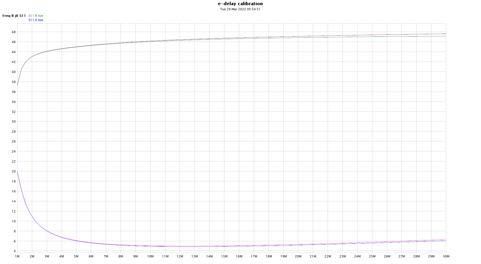
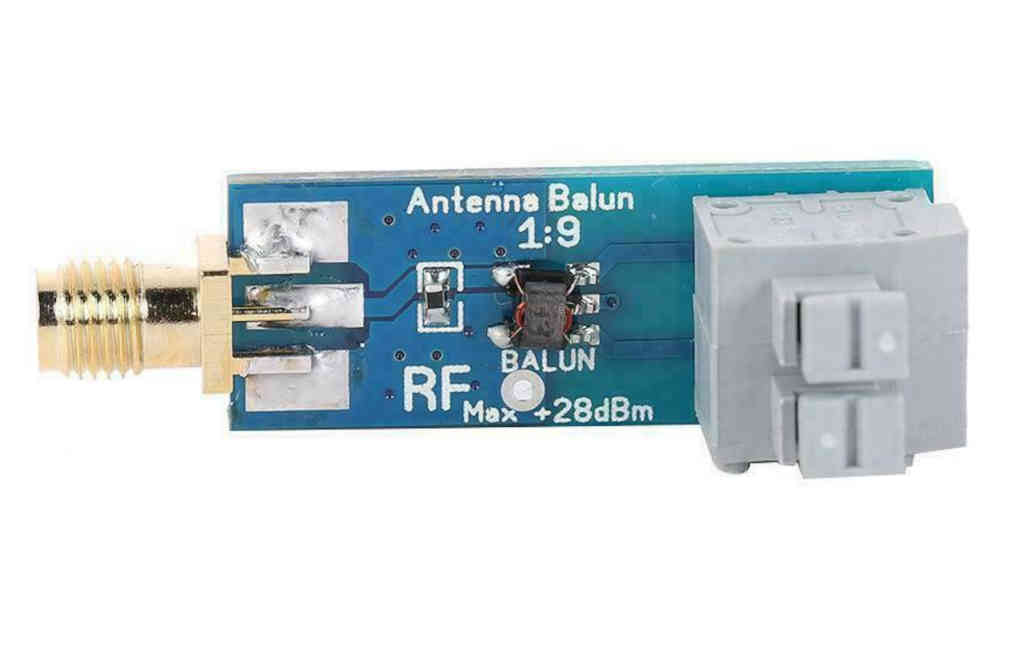
The article InsertionVSWR of Chinese 1:9 balun module #2 gave a plot of R,X where the reference plane was at the compensation capacitor on the module. Recall that the transformer was actually 1:4.
Ideally you might OSL calibrate the fixture at that point, or at the transformer terminals to obtain a good picture of the transformer response, but it is not convenient to be desoldering the transformer or cutting tracks, so there is a fairly good alternative at the frequencies being discussed (1-30MHz).

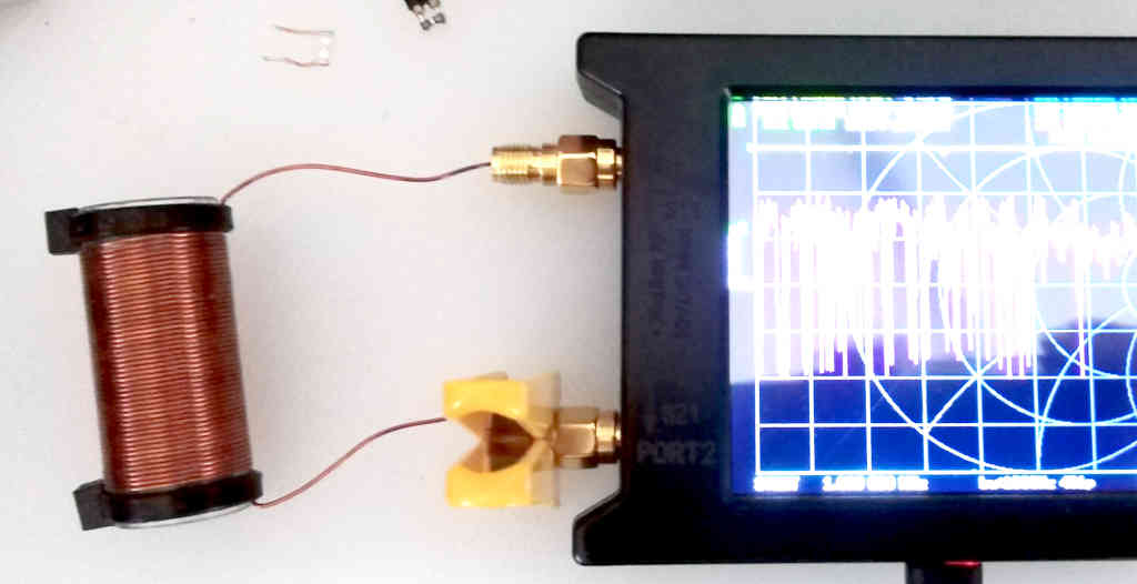
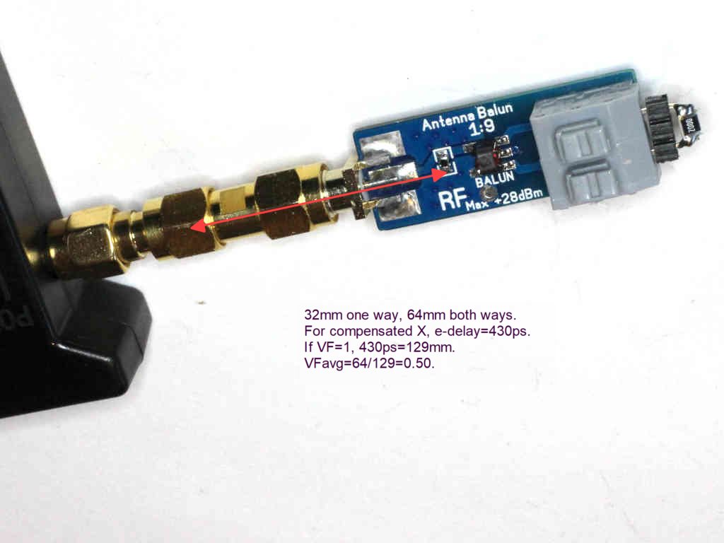
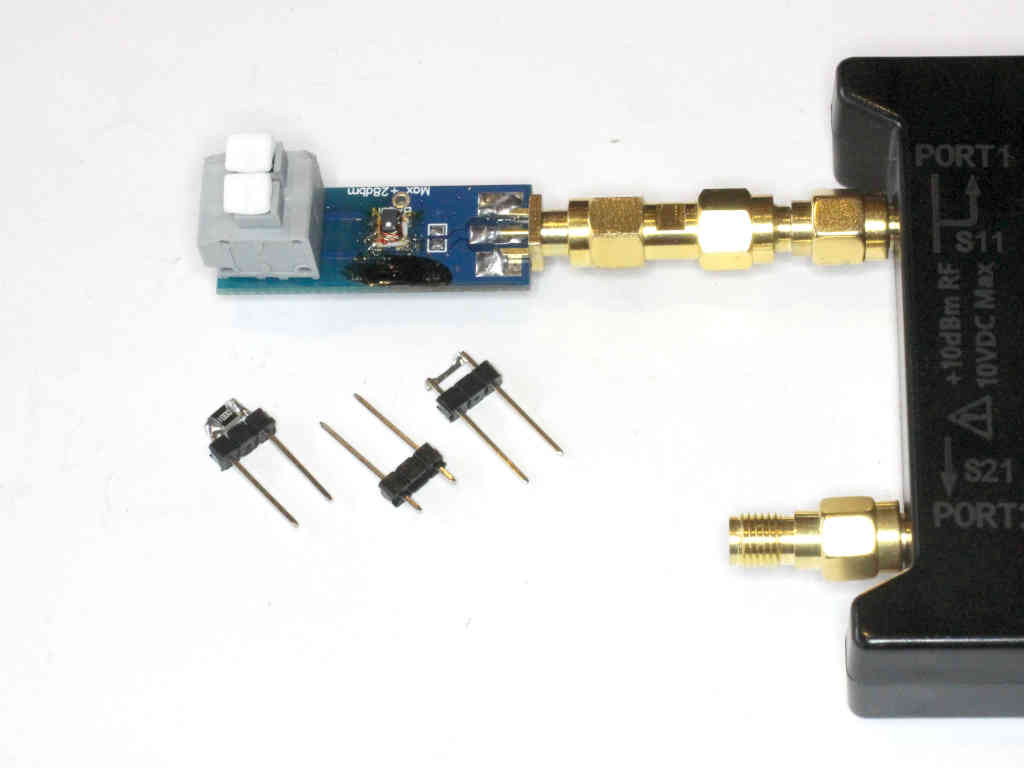
Above is an annotated pic of the test setup. The NanoVNA is calibrated at the Port 1 connector (in fact the outboard end of the SMA savers that are never removed), and the desired reference plane is some 32mm away of transmission line of segments of uncertain Zo and loss.
Firstly, the loss will be very low, so we can simply deal with the time delay that the fixture introduces.
The NanoVNA-H4 with DiSlord v1.1.0 firmware has a facility for port extension (though it is not called that, it is called e-delay), as does the NanoVNA-App software used. In both cases, the value of e-delay converted to phase is subtracted from the s11 measurement at each frequency, and the result is correction for the port extension delay.
Note that this:
- does not compensate amplitude change, so it is only accurate where loss is very low; and
- assumes that the port extension has Zo=50+j0Ω though mixed Zo does not cause significant errors if the transmission line sections are very short.
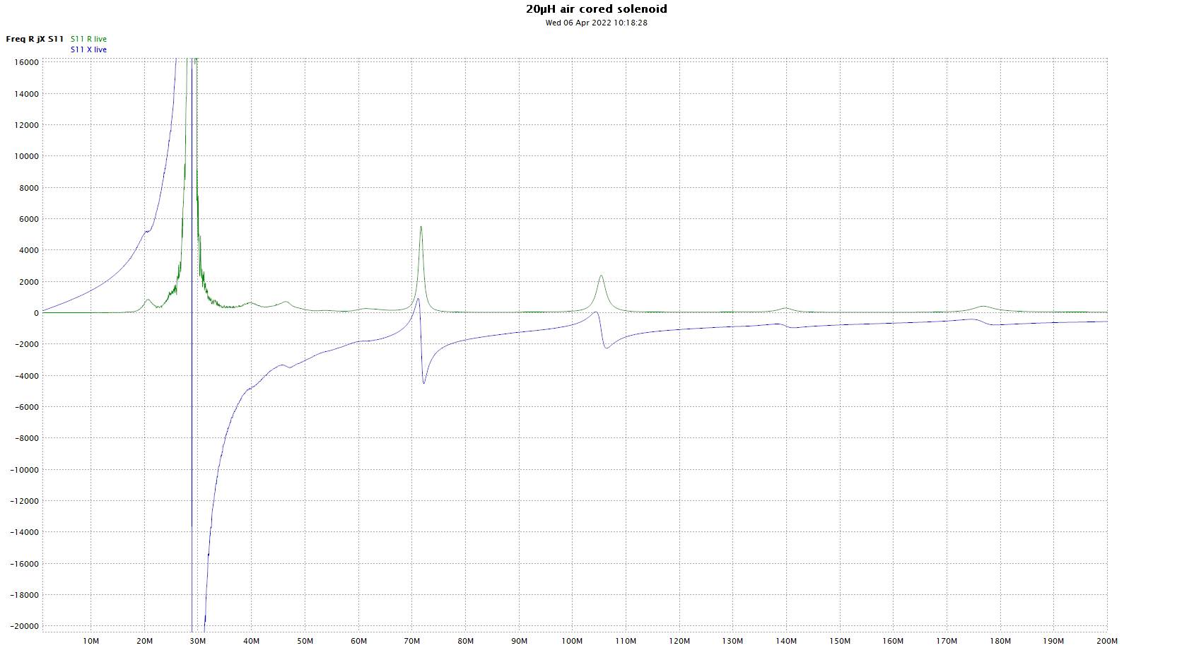
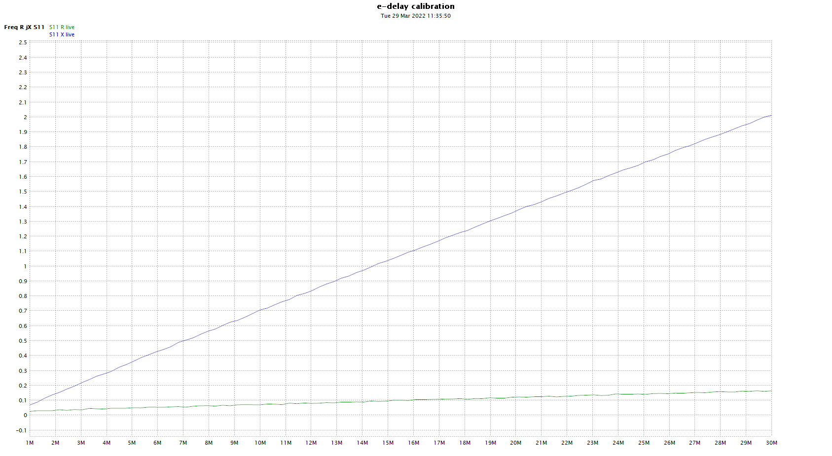
Let’s apply a temporary short circuit the the compensation capacitor at the reference point.

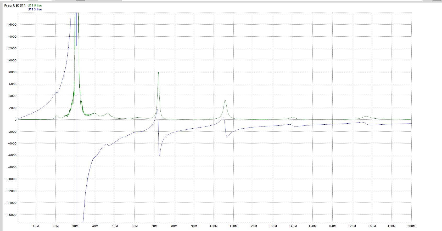
We want X=0, the rising X is due to the transmission line transformation within the test fixture, and that transformation will render any uncompensated impedance values incorrect (though the ReturnLoss and VSWR will be correct).
Lets look at the phase of s11 for the same case, remembering that the phase of the short circuit should be 180°.

s11 lags 180° by 4.6° @ 30MHz, we can calculate the time equivalent: \(t=\frac{\phi}{2 \pi f}=\frac{4.6 \pi}{360 \pi f}=\frac{4.6}{360 f}=426 \text{e-9s}\), so 426ns is a good starting point for e-delay.
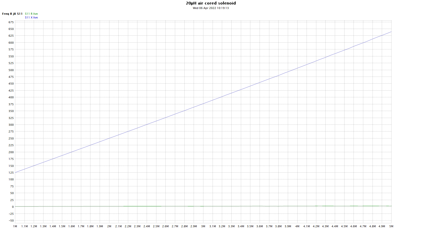
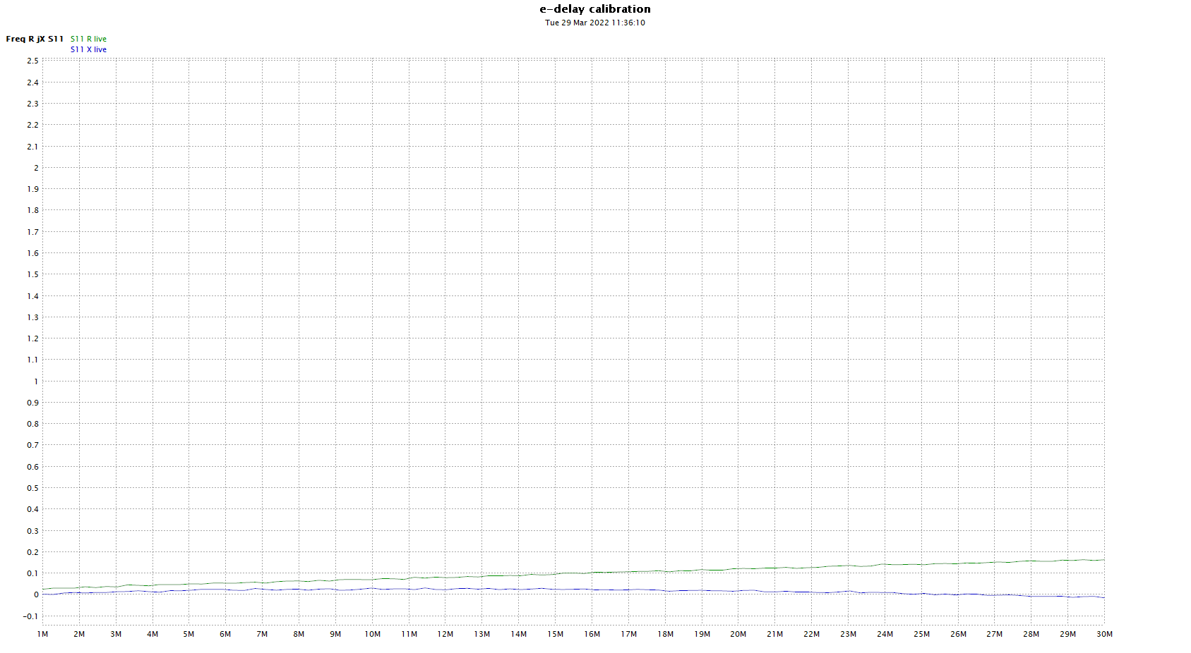
Ok, returning to the R,X chart and adjusting e-delay around 426ns for best X plot…

Above, 430ns is pretty acceptable.
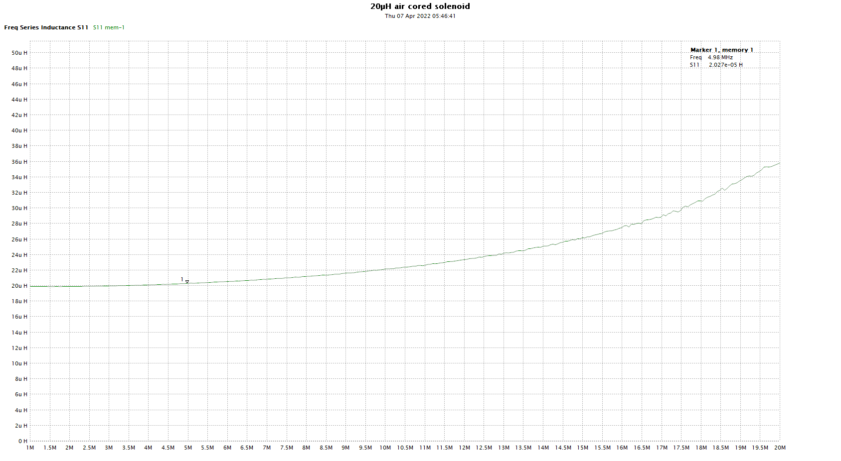
Having backed out the delay of the fixture, lets look at R,X.

Above, R,X with and without the e-delay adjustment. The difference is quite small in this case (the lower R and X @ 30MHz are the e-delay corrected values).
Applying the calibration short circuit
In the experiment above, an X-ACTO #16 knife was used to bridge both sides of the capacitor mentioned. The same technique can be used to bond a track to an adjacent ground track (the knife will cut through the solder mask).
A selection of short circuit coax adapters, M & F, can be very handy when making measurements.
For example, to measure an antenna with a UHF female connector, a short cable with adapters SMA(M) for the VNA to UHF(M) for the antenna can be calibrated with a UHF(F) SC (made simply with a panel jack and the back side shorted with several copper conductors soldered as close to the insulator as possible).
Even if the place where you can conveniently apply the reference SC is not exactly where you want it, if the further extension is something you can characterise well (like a measurable length of known 50Ω line with known VF) you can further tweak the e-delay setting.
For example, to measure an antenna with a UHF female connector on a 400mm pigtail of Belden 8267 (RG213) from its actual feed point, a short cable with adapters SMA(M) for the VNA to UHF(M) for the antenna can be calibrated with a UHF(F) SC. Having found the appropriate e-delay to the applied short circuit, calculate the one-way delay of the coax pigtail. Using TLLC we get 2022ps, so the round trip delay is 4044ps. Now add that 4044ps to the e-delay to the applied short to get the appropriate e-delay to the actual feed point.
Summary
The NanoVNA-H4 with DiSlord v1.1.0 firmware has a facility for port extension (though it is not called that, it is called e-delay), as does the NanoVNA-App software used here. In both cases, the value of e-delay converted to phase is subtracted from the s11 measurement at each frequency, and the result is correction for the port extension delay.
Note that this:
- does not compensate amplitude change, so it is only accurate where loss is very low; and
- assumes that the port extension has Zo=50+j0Ω though mixed Zo does not cause significant errors if the transmission line sections are low loss, close to Zo=50+j0Ω, and very short.
The technique may provide a means of moving the reference plane with acceptable accuracy.
Last update: 15th May, 2022, 9:43 AM