Baluns – wire size insanity

An online expert recently expounded on detailed design of a balun, this is an excerpt about wire sizing.

The wire gauge used limits the current handling capacity of the wire, run too thin a wire and it will heat up. Run much too thin of a wire for the power in use and it will fuse open. Current carrying capacity of wire is typically rated for either power transmission applications or chassis wiring applications. The latter, and higher, current capacity for a wire is relevant to designing a balun. How much current your 50 watt signal generates depends on the impedance its looking into. If you’re talking about a 50 ohm system, with a perfect match you’ll deliver one amp through your balun wires when driving 50 watts into it. Allowing for say a 4:1 SWR the worst case current(@12.5 ohms) is 2 amps. If you’re using this as a tuner balun, perhaps to drive a multi-band doublet then the impedance can vary widely so over sizing the wires is easy insurance. Here’s a table of wire current carrying capability: https://www.powerstream.com/Wire_Size.htm

For convenience, the relevant part of the table linked above is quoted for discussion.

So, the poster recommends wire with chassis wiring rating of 2A for 50W with reserve capacity for worst case VSWR=4. Continue reading Baluns – wire size insanity

Review of the Amidon AB_200_10 balun

The Amidon AB_200_10 2-30MHz, 1KW balun and knock-offs have been around for a very long time, I recall Dick Smith selling them in the early 1970s in Australia.

They were regarded as the epitome of the art… but it was not a very well understood art.

Lets analyse the common implementation as a Ruthroff 4:1 voltage balun in a 50:200Ω scenario.

Ruthroff 4:1 voltage balun

In this implementation, Amidon’s instructions show 16 bifilar turns on a T200-2 core.

A very simple model is to consider the device as an ideal transformer with a shunt magnetising impedance equal to the impedance of the 16t winding that appears across the 50Ω terminals. This has its greatest effect at low frequencies and although it is specified from 2-30MHz, lets analyse it at 3.5MHz.

The powdered iron core has very low loss at 3.5MHz, sufficiently so that we can ignore the imaginary component of µr for this analysis and take µr to be 10+j0.

Above is a calculation of the magnetising impedance and admittance under those assumptions. The magnetising admittance (0.00-j0.0134S) appears in shunt with the transformed load admittance (0.02S) so we can simply add them to find the admittance seen by the transmitter (0.02-j0.0134S). Continue reading Review of the Amidon AB_200_10 balun

A low Insertion VSWR high Zcm Guanella 1:1 balun for HF – more detail

This article expands on the detail behind A low Insertion VSWR high Zcm Guanella 1:1 balun for HF.

Choice of core

Online experts all have a preferred core material, but there is a dearth of measurement data to show the difference in actual use. If someone recommends a particular core material and cannot provide measured Zcm data to support the recommendation, regard it as a weak recommendation.

Beware the magic of unobtainium… just because something is hard to get is not an indication that it is desirable.

Above is the complex permeability characteristic of the #43 material used. Inductance calculators that do not take that frequency dependent complex characterisitic into consideration produce invalid results. (Duffy 2015) gives a suitable approximation, and there are links to calculators that do work properly at the bottom of this article. Continue reading A low Insertion VSWR high Zcm Guanella 1:1 balun for HF – more detail

A low Insertion VSWR high Zcm Guanella 1:1 balun for HF

This article describes a Guanella 1:1 current balun which has high common mode impedance (Zcm) and low Insertion VSWR. It is for application on antennas that have low VSWR50 on at least some bands, especially if they would be used without an ATU on some bands.

The purpose of the balun is to minimise common mode feed line current which may contribute to EMC problems when transmitting, and contribute to increased ambient noise when receiving. Reduction of feed line common mode current also helps in achievement of expected load impedance characteristic, radiation pattern and gain. This article gives measured Zcm, but the definitive test of the effectiveness of such a balun is direct measurement of common mode current Icm… and it is so easy.

Example applications are half wave centre fed dipoles, fan dipoles, trapped dipoles, G5RV with hybrid feed, ZS6BKW, trapped verticals, monopoles, ground planes.

To obtain low Insertion VSWR, the choke will be wound with 50Ω coax, to demonstrate the practicality of the design budget (but good quality) regular (ie solid PE dielectric) RG58C/U will be used. Foam dielectric is NOT recommended. Solid PTFE coax could be used, but avoid coax with steel cored inner conductor, it may be lossier than you think at low frequencies with the silver cladding is relatively thin.

The candidate core is the readily available FT240-43 (Fair-rite 2643803802, 5943003801), it is a low cost NiZn ferrite with medium µr, and its µr and loss characteristic contributes to a broad high impedance choke well suited to this application.

Above is a model of the expected Zcm with 11 turns of RG58C/U coax and an equivalent shunt capacitance of 4.6pF. Continue reading A low Insertion VSWR high Zcm Guanella 1:1 balun for HF

G3LNP balun with symmetric ‘matched’ load

My article G3LNP balun explored the operation of the G3LNP 4:1 balun on a 200Ω asymmetric load and found it exhibited extreme Insertion VSWR on what should have been an ideal impedance transformation but for the asymmetric element.

The balun is in fact a Voltage Balun and cannot be expected to work properly on asymmetric loads.

A correspondent proposes that the balun probably works very well on a nearly symmetric load such as a half wave dipole.

There are two aspectes to this proposition:

  1. the assumption that a common half wave dipole implementation is nearly symmetric; and
  2. the balun works well on a nearly symmetric load.

Continue reading G3LNP balun with symmetric ‘matched’ load

G3LNP balun

G3LNP described a 4:1 balun for HF antennas in Radcom Nov 2017.

Above is the schematic supplied by G3LNP. He describes the dashed link at the bottom as optional, but uses it in his prototype so this analysis is with that link installed. The prototype used equal lengths of coax (1m PF100, an RG-6 like coax), and the toroidal choke appears to be 8t on a T130-2 powdered iron core.

Exploration of behaviour of baluns on extreme asymmetric load often reveals whether they work properly for asymmetric loads.
Continue reading G3LNP balun

Common mode impedance of W2DU baluns

Walt Maxwell (W2DU) described a simple common mode choke or 1:1 current balun using ferrite sleeves slipped over a coaxial cable.

Fig 1:

Maxwell gives the choking impedance of two of his recommended chokes in Fig 21-3 from (Maxwell 2001). He does not give any detail of how he arrived at the curves, and in correspondence declined to give any detail.

This article focusses on a linear design for HF using 50 x FB-73-2401 (2673002402) ferrite sleeves.

The question that arises is how do you measure the impedance of a component that is 250+mm between terminals. Continue reading Common mode impedance of W2DU baluns

Thoughts on binocular ferrite core inductors at radio frequencies

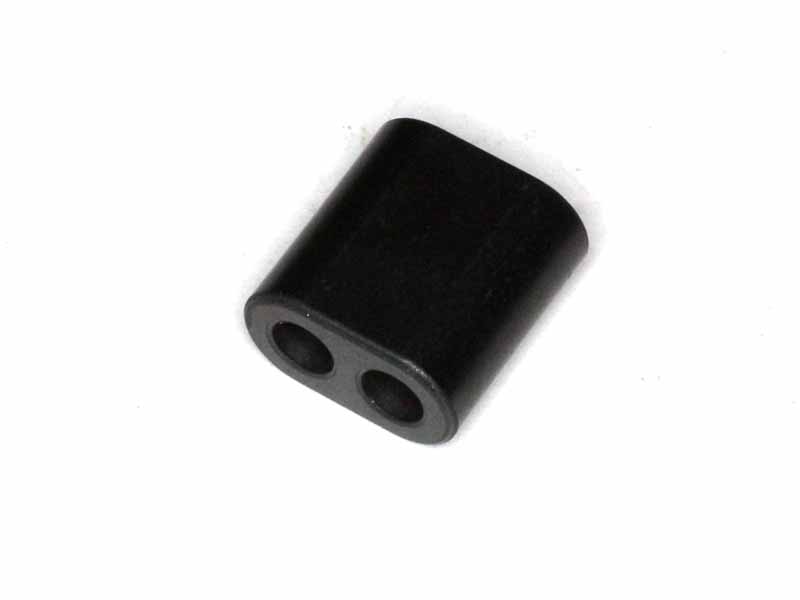
Binocular ferrite cores are widely used, but not so widely understood.

Understanding inductors is an important first step to understanding transformers are they are coupled inductors.

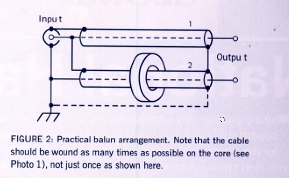
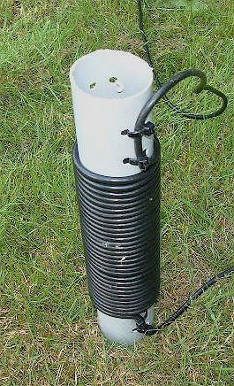
The usual use of them is to make a winding of several turns around the central limb. One turn is a pass through both sides of the core around the central limb. Figures given in datasheets for Al or impedance rely upon that meaning of one turn.

A common assumption is that L=Al*n^2.

Note that published Al values are obtained by measurement typically at 10kHz and are not directly applicable at radio frequencies for core materials where the permeability µ is significantly different to µi (most ferrites). Notwithstanding this fact, most inductance calculators assume µ is not frequency dependent.

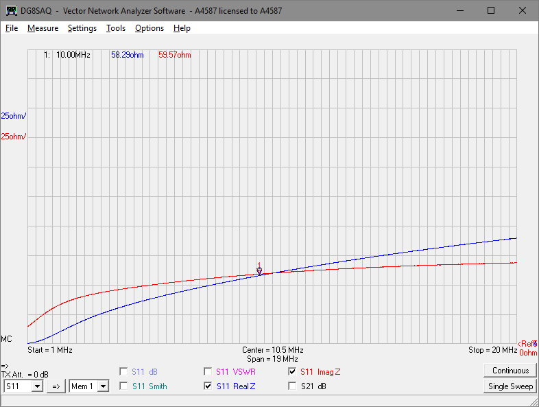
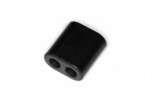
Let us measure a one turn winding on a practical binocular core for reference

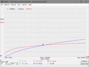
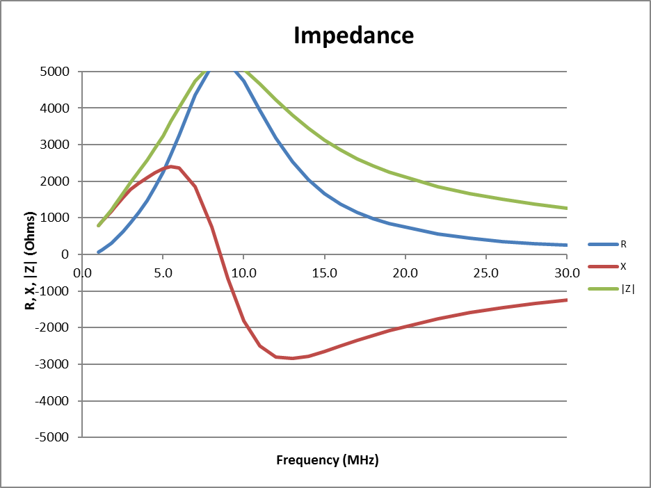
Above is a measurement of R,X of a BN43-202 core with a one turn winding at 10MHz. X is  59.57Ω implying inductance of 0.95µH (assuming a simple two component model which does not capture self resonance effects). Datasheets for this core specify Al as 2200nH for one turn, yet we measure 950nH at 10MHz… proof of problems in simple application of Al.

Of course it is possible to make an inductor by passing a conductor once though one side of the binocular, a half turn if you like, but don’t let that label imply the impedance relative to a one turn winding.

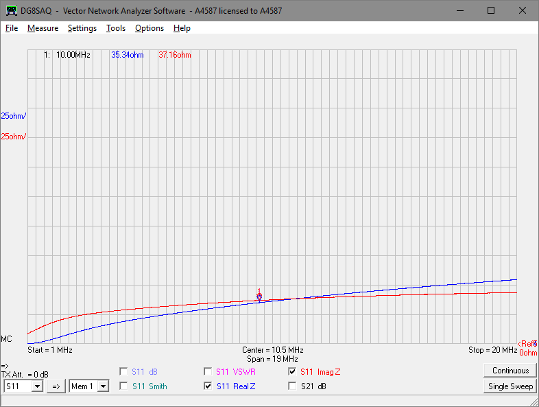
Above is a measurement of a BN43-202 core with a ‘half turn’ winding.

If inductance followed the formula L=Al*n^2 and this was truly a half turn winding, we would expect the inductive reactance X ( 37.16Ω) to be one quarter or 25% of that of the single turn inductor (59.57Ω). Clearly it is not, it is 62%, the notion of a half turn or the formula or both have failed badly in this case.

Well on the back of that failure, lets try 1.5t.

Would we be brave or foolish to predict inductance will be 1.5^2 times that for one turn?

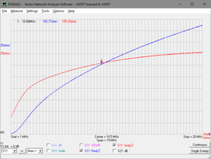
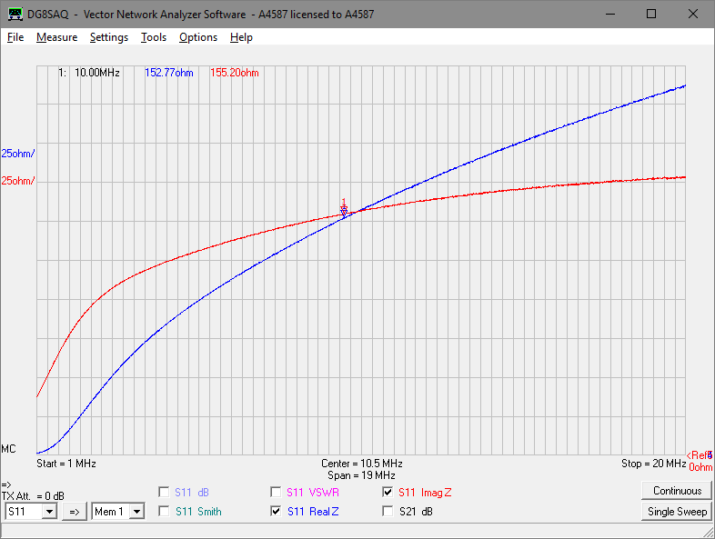
Above is a measurement of a BN43-202 core with a ‘one and a half turn’ winding.

If inductance followed the formula L=Al*n^2 and this was truly a half turn winding, we would expect the inductive reactance X ( 155.2Ω) to be 1.5^2 or 2.25 times that of the single turn inductor (59.57Ω). Clearly it is not, it is 2.60 times, the notion of a half turn or the formula or both have failed badly in this case.

Now let us look at Q, the ratio of X/R. The Q of the half turn inductor is 1.051, the one turn inductor is 1.022, and the one and a half turn inductor is 1.016. The quite small decrease in Q may be entirely due to the lower self resonant frequency as more turns are added and may not indicate a significant increase in core loss because of ‘half turn effects’ as sometimes claimed.

The error in conventional n^2 estimates of odd half turns becomes less significant with higher turns.

Conclusions

The traditional formula L=Al*n^2 does not apply to ferrite binocular cores at radio frequencies for odd half turns, and does not account for variation of permeability with frequency or influence of self resonance.

Understanding inductors is the first step to understanding transformers are they are coupled inductors.

G4YDM balun

G4YDM described his balun at Ham Radio – What Is a Balun and How to Make One Cheaply.

With a title like that it is sure to have wide appeal, but it isn’t anything too novel, it is simply an air solenoid of 50Ω coax cable as a common mode choke, commonly known as an Ugly Balun.

He gives some instructions for one of several constructions:

When wrapping your coax around the pipe don’t use too much force as it may damage the inner braid and space the turns away from each other by a millimetre or two. R-G-2-1-3 coax around 21 feet used with 5 inch pipe will handle 400 watts pf power.

Above is a pic of the third construction which appears to be 21′ of RG213 on a 5″ PVC former:

He gives some performance measurements adjacent to the pic above:

Using a dummy load connected to the choke and transmitting 100 watts from my transmitter indicated an S.W.R. readings of around 1.5 to 1 at 3.5 Megahertz when testing 28 Megahertz the S.W.R. reading came down to 1.1 to 1 which is an excellent match. …

The test described above seems to simply be a dummy load connected to one end of 21′ of RG213 and the transmitter with VSWR meter feeding the other end. To be meaningful we need to know the impedance of the dummy load, indeed to be meaningful it needs to be 50Ω, so lets assume that is the case. Continue reading G4YDM balun

Coil32 inductance calculator

A recent online posting gave unequivocal recommendation for the Coil32 Inductance Calculator for application to a ferrite toroidal HF current balun.

Always interested in these things, I tried to download it to evaluate it but there was rigmorol to create an account and aware that I have never downloaded a calculator that handled that specific problem at all well, I was reluctant.

They do however have some online calculators that are supposed to use the same algorithms and methods as the downloadable software, so lets review the one for a toroidal ferrite inductor.

screenshot-07_11_16-16_21_15

Above is the data entry form, and warning bells sound. The “relative magnetic permeability” field is a simple scalar quantity, but the permeability of most ferrites at HF needs to be considered as a complex value (ie having real and imaginary components). Continue reading Coil32 inductance calculator