On testing coax cable loss with an analyser / VNA – part 3

On testing coax cable loss with an analyser / VNA – part 2 gave a method of approximating the matched line loss (MLL) of a section of transmission line based on measurements of ReturnLoss with the section terminated in both an open circuit and short circuit. The article demonstrated the method using TLLC to provide expected measurement values.

So, does it work in practice?

Let’s measure a 10m length of Belden 8267 (RG-213) fitted with N connectors using a Rigexpert AA-600 and an instrument grade N(F) short circuit.

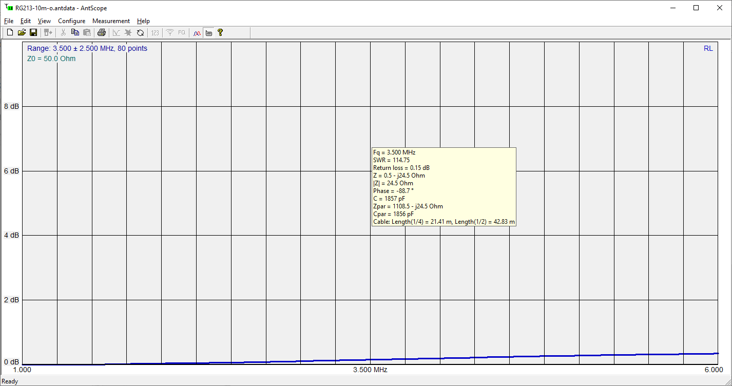
ReturnLoss @ 3.5MHz is 0.15dB. Continue reading On testing coax cable loss with an analyser / VNA – part 3

On testing coax cable loss with an analyser / VNA – part 2

On testing coax cable loss with an analyser / VNA – part 1 questioned a common method of measuring Matched Line Loss (MLL) of a section of an open circuit transmission line section, posing the questions:

The example gives MLL’ (based on half ReturnLoss) of about two thirds cable MLL.

  • Why is that?

  • What does it say for the measurement technique?

Continue reading On testing coax cable loss with an analyser / VNA – part 2

On testing coax cable loss with an analyser / VNA – part 1

A recent online video provides instruction on how to measure loss of a section of coax cable, loss to mean Matched Line Loss, \(MLL=\frac{P_{in}}{P_{out}}\) when the cable is terminated in its characteristic impedance Zo, and which can be expressed in db as \(MLL=10 log_{10} \frac{P_{in}}{P_{out}}\). Note that MLL in dB is ALWAYS a +ve value for a passive DUT such as this.

There is nothing new in the method, it appears in lots of analyser user manuals, and has a built in assist in many analysers.

The video deals with the case of an antenna analyser that has a ‘measure cable loss’ function and using a VNA. Lets use the VNA graphic as it shows more detail of what is happening.

Above is the video’s graphic for the case. The narration says to use the dB magnitude of s11 or ReturnLoss as equivalents. They aren’t equivalent (a hammy Sammy thing), \(ReturnLoss=-20 log_{10}|s11|\) or \(ReturnLoss_{dB}=-s11mag_{dB}\) (both wrt the VNA reference impedance). Continue reading On testing coax cable loss with an analyser / VNA – part 1

Measuring a 1/4 wave balanced line – nanoVNA

A question was asked recently online:

I am about to measure a 1/4 wave of 450 ohm windowed twinlead for the 2m band using my NanoVNA. My question is, since I will be making an unbalanced to balanced connection, should I use a common mode choke, balun or add ferrites to the coax side to make the connection, or does it really matter at 2m frequencies? The coax lead from my VNA to the twinlead will be about 6″ to 12″ long. I will probably terminate the coax in two short wires to connect to the twinlead.

It is a common enough question and includes some related issues that are worthy of discussion. Continue reading Measuring a 1/4 wave balanced line – nanoVNA

Measure transmission line Zo – nanoVNA – PVC speaker twin – loss models comparison #3

Measure transmission line Zo – nanoVNA – PVC speaker twin demonstrated measurement of transmission line parameters of a sample of line based on measurement of the input impedances of a section of line with both a short circuit and open circuit termination. From Zsc and Zoc we can calculate the Zo, and the complex propagation constant \(\gamma=\alpha + \jmath \beta\), and from that, MLL.

Above is a plot of: Continue reading Measure transmission line Zo – nanoVNA – PVC speaker twin – loss models comparison #3

Measure transmission line Zo – nanoVNA – PVC speaker twin – loss model derivation

The article Measure transmission line Zo – nanoVNA – PVC speaker twin demonstrated measurement of transmission line parameters of a sample of line based on measurement of the input impedances of a section of line with both a short circuit and open circuit termination. From Zsc and Zoc we can calculate the Zo, and the complex propagation constant \(\gamma=\alpha + \jmath \beta\), and from that, MLL.

Measurement with nanoVNA

So, let’s measure a sample of 14×0.14, 0.22mm^2, 0.5mm dia PVC insulated small speaker twin.

Above is the nanoVNA setup for measurement. Note that common mode current on the transmission line is likely to impact the measured Zin significantly at some frequencies, the transformer balun (A 1:1 RF transformer for measurements – based on noelec 1:9 balun assembly) is to minimise the risk of that. Nevertheless, it is wise to critically review the measured |s11| for signs of ‘antenna effect’ due to common mode current. Continue reading Measure transmission line Zo – nanoVNA – PVC speaker twin – loss model derivation

An interesting study in the effect of fixture on impedance measurement

A chap posted a pic and some mini VNA measurement results of a resistor which he reported has a DC resistance of 80Ω.

Above is part of the pic, focusing on the ‘fixture’. The chap reports that the VNA was OSL calibrated, and we might assume that was at the SMA(M) connector (it is difficult to explain the results if the reference plane was at the VNA jack). Continue reading An interesting study in the effect of fixture on impedance measurement

A common scheme for narrow band match of an end fed high Z antenna – surely it is a 1:9 transformer?

A reader of A common scheme for narrow band match of an end fed high Z antenna commented:

…if the coil is tapped at 1/3, surely then the coil is a 1:3^2 or 1:9 transformer and the capacitor simply ‘tunes out’ the coil reactance, what is the input impedance when it has a 450+j0Ω load?

That is very easy to calculate in the existing Simsmith model.

Above, with load of 450+j0Ω, the input impedance at 50MHz is 8.78+j34.36Ω (VSWR50=8.4), nothing like 50+j0Ω. Continue reading A common scheme for narrow band match of an end fed high Z antenna – surely it is a 1:9 transformer?

A common scheme for narrow band match of an end fed high Z antenna

This article discusses the kind of matching network in the following figure.

A common variant shows no capacitor… but for most loads, the capacitance is essential to its operation, even if it is incidental to the inductor or as often the case, supplied by the mounting arrangement of a vertical radiator tube to the mast. Continue reading A common scheme for narrow band match of an end fed high Z antenna