OCF short vertical dipole for HF

The OCF short vertical dipole for HF has become popular, particularly disguised as a flag pole for low impact installations and encouraged by claims of outstanding performance. The antenna was described in QST and a commercial version was available at time of writing.

The rationale for the design is that it is a short dipole, not requiring radials, and feed point offset downwards by 30% as an optimal value for performance (driven by often unsound assessments of coax loss).

Claims include:

Off-Center Fed Vertical Dipole design means no radials, 90% efficient or better across 80m – 10m

clip-227

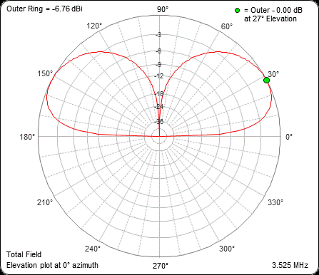
Above is the promising gain plot for one of the commercial implementations, it is only one S point (6dB) behind a quarter wave vertical with 4 buried radials. Continue reading OCF short vertical dipole for HF

Cadweld Plus Control Unit

cadwelpluscu

The CADWELDPLUSCU is the igniter for the Cadweld Plus line of electrically initiated thermite weld capsules. The plug seen on the end of the cable slides over the flat connection strip to the capsule.

cadweld32

The environment around the weld crucible is subject to a sudden ejection of hot gases and smoke, much of which is emitted out of the slot in a Oneshot crucible intended for the connection strip, and this is only a 45g capsule. There is probably less gas emitted towards the connector on reusable moulds as the gap for the connection strip is very narrow.

cadweldpluscuplug01

Despite dressing the plug away from the stream of hot gasses emitted, it can be seen above that the plug has suffered heat damage. Of particular concern is deformation of the parts at the cable clamp rendering it less effective. The plugs come on a new lead set that is relatively expensive.

Since one wants to be able to yank the cord away from the crucible as soon as possible to minimise heat damage, the cord grip needs to be effective.

This article describes two measures taken to protect the plug and ensure the cord grip works. Continue reading Cadweld Plus Control Unit

MFJ-993B internal balun review

The MFJ-993B auto antenna tuner includes an internal balun, this article is a review of that balun.

screenshot-29_09_16-10_02_24The schematic shows the balun as a Guanella 4:1 balun with the usual external link to one of the coaxial antenna sockets. (The label “Z balanced” is misleading, clearly one of the terminals is grounded and this is the unbalanced connection to the coax connector via a link. The antenna connects to the left hand terminals.)

Unlike almost all ATUs with an internal balun, this is a current balun (to their credit), but a 4:1 balun.

There are two aspects of balun behaviour that are of particular interest:

  • choking or common mode impedance; and
  • impedance transformation.

Continue reading MFJ-993B internal balun review

Shack entry / ATU configuration for my G5RV with tuned feeder

At MFJ-993B on my G5RV with tuned feeder I discussed first impressions of the replacement ATU.

This article documents the physical layout.

The antenna is a G5RV with tuned feeders (Varney 1958). The tuned feeder is home made two wire line using 2mm diameter copper spaced 50mm.

img_0594

Above at the right, the open wire line terminates on a home made balun on the feed line entrance panel, see
Design / build project: Guanella 1:1 ‘tuner balun for HF’ – #4 for details of the balun. This is all under the building eaves, but it is waterproof… the area is regularly jetted with high pressure water to clean insects away. Continue reading Shack entry / ATU configuration for my G5RV with tuned feeder

Z0 of two wire line

I saw a recent discussion where the blind were leading the blind on the dimensions of a twisted two wire line for Z0=50Ω for use in a balun.

The poster had used an online calculator which used the well known log function for estimating Z0 of an air spaced two wire line… the calculator, like most quotations of the formula do not state clearly that it is only an approximation of limited validity, and the calculator returned results for ridiculous inputs (like negative spacing).

clip-221

The graph above (Duffy 2008) shows the log approximation, and the underlying acosh based estimate. I say estimate because the acosh function does not account for proximity effect which becomes significant at the very closest spacings, and internal inductance which becomes significant at lower frequencies. Proximity effect depends on more than just the spacing/diameter ratio and so cannot be shown on the above graph.

So how did our poster find dimensions for wires for Z0=50Ω when the log graph above shows that as the wire centre to centre spacing approaches the wire diameter, it the wires approach touching, Z0 approaches 83Ω? Continue reading Z0 of two wire line

The sign of Return Loss

I was browsing a ham forum recently when I came across a Return Loss plot apparently from a ham grade miniVNA Tiny.

Lets just remind ourselves of the meaning of the term Return Loss. (IEEE 1988) defines Return Loss as:

(1) (data transmission) (A) At a discontinuity in a transmission system the difference between the power incident upon the discontinuity. (B) The ratio in decibels of the power incident upon the discontinuity to the power reflected from the discontinuity. Note: This ratio is also the square of the reciprocal to the magnitude of the reflection coefficient. (C) More broadly, the return loss is a measure of the dissimilarity between two impedances, being equal to the number of decibels that corresponds to the scalar value of the reciprocal of the reflection coefficient, and hence being expressed by the following formula:

20*log10|(Z1+Z2)/(Z1-Z2)| decibel

where Z1 and Z2 = the two impedances.

(2) (or gain) (waveguide). The ratio of incident to reflected power at a reference plane of a network.

Return Loss expressed in dB wrt a real reference impedance will ALWAYS be a positive number in passive networks.

Return Loss according to the miniVNA Tiny

clip-220

Above, the miniVNA Tiny presents Return Loss as a negative value. Continue reading The sign of Return Loss

Is the premises main earthing conductor ok as a lightning down conductor

Upon reading Rationale for sizing of lightning down conductor a correspondent asks whether his premises 4mm^2 main earthing conductor ok as a lightning down conductor.

Intended purpose of electrical installation ground electrode

The usual source of current on the premises main earth conductor would be a fault energised by the incoming supply. To understand the implications, lets review the supply system. Continue reading Is the premises main earthing conductor ok as a lightning down conductor

Rationale for sizing of lightning down conductor

The lightning ground conductor shown at Mast ground rework might at first seem excessive, this article sets out the rationale.

GroundRod02

The connection to a 2.4m copper clad steel driven electrode (under the green cover) is 35mm^2 copper.

The nature of lightning protection sizing

Lightning protection sizing is a risk management regime driven by the mechanisms of lightning and variation in distribution.

It is not surprising then that regulatory standards in different distributions broadly use similar design methods but set different practices for implementation in the jurisdiction.

So, let’s go standards shopping… what we are looking for is guidance on the energy (or work) that is directed to heating the down conductor, and choosing a conductor size that will sustain not just a single stroke, or an average stroke, but most events that may include many strokes in a short period of time. Continue reading Rationale for sizing of lightning down conductor