Icom IC-7410 – PTT tuner start doesn’t work

I have an IC-7410 with R1 of the firmware installed.

I have attempted to use its PTT tuner start feature (triggers ATU tune on PTT if frequency changed a significant amount)  with an MFJ-993B ATU, but it fails.

The symptoms are that the IC-7410 does not transmit its tune carrier, it remains in the mode active when PTT was pressed.

Tuner operations initiated from the IC-7410 TUNE switch appear to all work as expected.

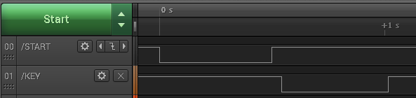
Above is a logic trace of the ATU control wires on PTT tune. everything looks good, when the /START signal is recognised as valid, the ATU asserts KEY and the IC-7410 should put tune carrier out… but it doesn’t and the ATU aborts after about 0.5s without tuning. Continue reading Icom IC-7410 – PTT tuner start doesn’t work

Speaker-microphones and DMR portables

Speaker-mics (RSM) are popular with portables (hand-helds), and it turns out that a lot of the implementations which appeared to work properly with conventional FM radios have issues on DMR portables.

The frustration in buying these things online is that sellers typically have no idea of what they are selling.

This article deals with degraded audio in a form that is often described as motor boating. Continue reading Speaker-microphones and DMR portables

Grebenkember’s original Tandem match

(Grebenkemper 1987) describes a directional coupler that has become very popular, especially in commercial implementation.

screenshot-22_11_16-07_23_25The simplified circuit above from Grebenkemper’s article illustrates the key elements of the directional coupler.

An important detail of the design is that the primary of the right hand transformer appears in shunt with the antenna load, and the magnetising impedance of that transformer core compromises Insertion VSWR. It is important that the magnetising impedance is sufficiently high (or the admittance sufficiently low) to not cause significant Insertion VSWR.
Continue reading Grebenkember’s original Tandem match

KitsAndParts.com QRP SWR bridge

The project is to build a test a couple of QRP VSWR detectors by KitsAndParts.com (http://www.kitsandparts.com/bridge.php) rated at 10W.

kitsandparts002

Above are the completed kits.

bridge_sch

Above is the schematic. The bridge uses a type of Sontheimer coupler (Sontheimer 1966) and these are commonly poorly designed. The first question is whether the magnetising impedance of T2 which appears in shunt with the load is sufficiently high to not give rise to poor insertion VSWR. Continue reading KitsAndParts.com QRP SWR bridge

Walter Maxwell’s teachings on system wide conjugate matching

Walt Maxwell (W2DU) made much of conjugate matching in antenna systems, he wrote of his volume in the preface to (Maxwell 2001 24.5):

It explains in great detail how the antenna tuner at the input terminals of the feed line provides a conjugate match at the antenna terminals, and tunes a non-resonant antenna to resonance while also providing an impedance match for the output of the transceiver.

Walt Maxwell made much of conjugate matching, and wrote often of it as though at some optimal adjustment of an ATU there was a system wide state of conjugate match conferred, that at each and every point in an antenna system the impedance looking towards the source was the conjugate of the impedance looking towards the load.

This is popularly held to be some nirvana, a heavenly state where transmitters are “happy” and all is good. Happiness of transmitters is often given in online discussion by hams as the raison d’être for ATUs . Continue reading Walter Maxwell’s teachings on system wide conjugate matching

Exploiting your antenna analyser #25

Find coax cable velocity factor using an antenna analyser without using SOL calibration

A common task is to measure the velocity factor of a sample of coaxial transmission line using an instrument without using SOL calibration.

Whilst this seems a trivial task with a modern antenna analyser, it seems to challenge many hams.

We will use a little test fixture that I made for measuring small components, and for which I have made test loads for SOL calibration. We will find the frequency where reactance passes through zero at the first parallel resonance of an O/C stub section, this is at a length of approximately λ/2 (a good approximation for low loss coaxial cables above about 10MHz).

We will use a little test fixture that I made for measuring small components, and for which I have made test loads for SOL calibration.

The text fixture used for this demonstration is constructed on a SMA(M) PCB connector using some machined pin connector strip and N(M)-SMA(F) adapters to connect to the instrument.

VfMeasurement01

Above is a pic of the test fixture with adapters (in this case on a AA-600). Continue reading Exploiting your antenna analyser #25

Exploiting your antenna analyser #24

Find coax cable velocity factor using an antenna analyser with SOL calibration

A common task is to measure the velocity factor of a sample of coaxial transmission line using an instrument that supports SOL calibration, an AIMuhf in this example.

Whilst this seems a trivial task with a modern antenna analyser, it seems to challenge many hams.

There are a thousand recipes, I am going to demonstrate just one that suits the instrument and application.

We will use a little test fixture that I made for measuring small components, and for which I have made test loads for SOL calibration. We will find the frequency where reactance passes through zero at the first parallel resonance of an O/C stub section, this is at a length of approximately λ/2 (a good approximation for low loss coaxial cables above about 10MHz).

The text fixture used for this demonstration is constructed on a SMA(M) PCB connector using some machined pin connector strip and N(M)-SMA(F) adapters to connect to the instrument.

VfMeasurement01

Above is a pic of the test fixture with adapters (in this case on a AA-600). Continue reading Exploiting your antenna analyser #24

Transmitter pulse generator for SSB RF PA adjustment

This article describes a pulse generator for adjustment of SSB RF power amplifiers.

The need

Valve RF power amplifiers usually use high voltage power supplies with poor regulation, and typically the voltage may sag by 10% or more on full power CW output, whilst on SSB telephony the voltage may sag a quarter of that.

The effect is that finding PA loading conditions for maximum power output on a key down CW signal optimises the loading for conditions that are significantly different to SSB telephony and not only is the maximum power output likely to be lower for key down CW, but it will be lower when used for SSB telephony than if it were adjusted using a drive that created full output power without sagging the power supply more than speech would.

Additionally, RF PAs intended for the amateur market cannot sustain key down CW for very long before overheating and sustaining damage forcing very short adjustment sessions. Adjustment at continuous maximum power puts great demands on a dummy load if one is being used.

So, to solve these problems, there are three objective:

  • create a drive / load scenario that is similar to SSB telephony conditions;
  • operate at reduced duty cycle to reduce internal heating of valves and power supply;
  • reduce the average dissipation requirements of a dummy load.

Continue reading Transmitter pulse generator for SSB RF PA adjustment

Exploiting your antenna analyser #23

Seeing recent discussion by online experts insisting that power relays are not suitable to RF prompts an interesting and relevant application of a good antenna analyser.

Screenshot - 03_08_16 , 14_12_56

Above is a sweep of an A/B changeover relay intended for HF application at up to 100W and lowish VSWR. The sweep is actually from 1 to 61MHz to be confident that there is not poor behaviour just outside of the HF range that might present on another implementation of the same design. Continue reading Exploiting your antenna analyser #23