Small untuned loop for receiving – is an amplifier necessary?

A correspondent reading recent articles on active loops for receiving asks:

I have a 30″ square loop of #12 wire that I use for receiving, and when I attach it to the receiver on 40m, the audio output voltage goes up three times or more. Do I need an amplifiers, or will it worsen things?

It is possible to determine the ambient noise temperature from the true noise power change over that of a matched termination.

The equivalent noise temperature of the receiver is implied by its Noise Figure when it is terminated with a matched termination. Noise due to an open circuit or short circuit input is not defined.

The correspondent re-measured with a termination, and as it turned out, the results were much the same, so lets work the case of voltage increasing by a factor of three.

Without going any further, we can calculate the degradation in External S/N by the receiver, total noise power is proportional to (3^2) times internal noise, so S/N degradation is 10*log(9/(9-1))=0.51dB… very little.

It is true that an amplifier is unlikely to improve things and will be likely to degrade things because of intermodulation distortion that is inherent in them, more so if it overloads on broadband signal input.

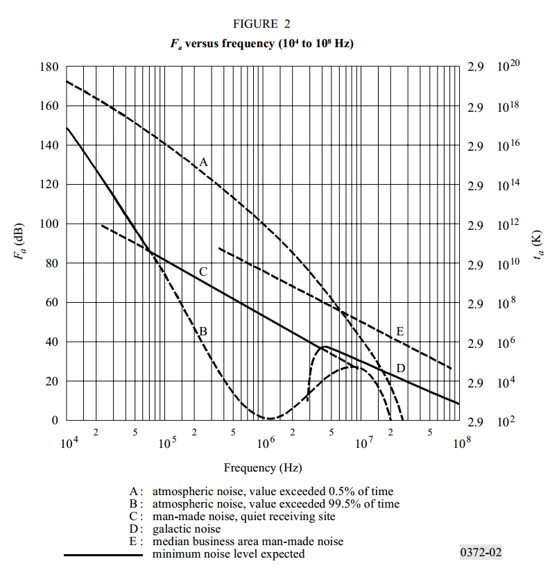
But let’s go on to estimate the ambient noise figure Fa.

It is really important for this process that the AGC does not change the receiver gain, and there is no overload or clipping. The latter means DO NOT SWITCH THE AGC OFF, the S meter deflects, you need extra input attenuation to keep things linear.

Now lets assume the receiver has a Noise Figure of 6dB (most modern HF transceivers are in that ball park).

We need to estimate the gain of the antenna, we will use Calculate small loop Antenna Factor.

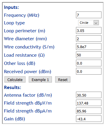
Ok, terminated in 50Ω, the untuned small loop has a gain of -43.4dBi. So, it captures only a very small portion of the external noise, but even so it delivers sufficient to the receiver to increase the output voltage by a factor of 3. Continue reading Small untuned loop for receiving – is an amplifier necessary?

ESP8266 relay module review – Yunshan WiFi relay

After scouring eBay for a packaged esp8266 with 220V 10A relay, two products were identified:

  • Yunshan WiFi relay; and
  • LC Technology relay.

As is usually the case, finding a schematic and specifications is very difficult and the sellers were of no help (no surprises).

The LC Technology device was offered with indistinct pics that hinted it had a 8Mb flash chip, ESP8266EX processor, and a STC 15F104 8 bit processor on board for some unidentified purpose.

A schematic was eventually located for the Yunshan board, and from pics it appeared to have a 12E module on it which hinted the flash size.

A Yunshan module was purchased for about $10 posted, and it was indeed a 12E with flash-id 4016, so 4MB of flash memory.

The board does not incorporate a USB-TTL adapter which is a nuisance not just requiring an external adapter for programming, but there is no integration of the RTS and DTR signals as in the NodeMCU devkit. Adding a quality USB adapter (eg CP2102) would not increase the price a lot, you can keep the CH340G etc). Continue reading ESP8266 relay module review – Yunshan WiFi relay

Small untuned loop for receiving – optimal loop load resistance

Small untuned loop for receiving set out a model for calculating the S/N degradation of an active untuned small loop antenna system.

The calculations in Small untuned loop for receiving – Trask noise and gain analysis might prompt the question of what is the optimal resistive load for an untuned small loop.

This article explores the topic for a simple model where the equivalent noise temperature of the amplifier is independent of source impedance.

A simple model for a small loop

We can construct a simple model where the loop behaves as a fixed  pure inductance, and its load is a fixed pure resistance.

This is a reasonably good model for a small loop, perimeter < wl/10, not too bad for perimeter up to wl/3.

The source impedance becomes the loop’s inductive reactance Xl which is proportional to frequency, and the load is Rl.

Above is a plot of the relative power developed in the load vs the ratio of Rl/Xl.

There is a maximum where Rl=Xl, and the power captured falls away either side. Continue reading Small untuned loop for receiving – optimal loop load resistance

Reset helper for NodeMCU ESP8266 modules

A common scheme for Lua scripted NodeMCU modules with automatically start the script init.lua is to incorporate some logic to test the condition of a GPIO pin to determine whether to boot to the application or drop to the lua prompt for programming etc. In fact the scheme can be elaborated to provide a simple multi level selection based on the time the input condition is applied.

The obvious pin to use is the pin that commonly has a “BOOT” or “FLASH” button on it, GPIO0 or D3. It is used to activate the ESP8266 boot loader if it is low during boot, so it must be left high at boot to allow the lua interpreter to run, but it can be pulled low shortly after boot up and tested from init.lua.

An example init script follows.

print("\n\nHold Pin00 low for 1s t0 stop boot.")
print("\n\nHold Pin00 low for 3s for config mode.")
tmr.delay(1000000)
if gpio.read(3) == 0 then
  print("Release to stop boot...")
  tmr.delay(1000000)
  if gpio.read(3) == 0 then
    print("Release now (wifi cfg)...")
    print("Starting wifi config mode...")
    dofile("wifi_setup.lua")
    return
  else
    print("...boot stopped")
    return
    end
  end
print("Starting app.lua")
dofile("app.lua")


Above is a pic of the helper. The DIP switch allows selection of the BOOT pulse in 1s increments. It has four connections, ground, Vdd, BootOut, and Reset (optional). The button near the DIP switch resets the helper which in turn will apply a 10ms reset pulse to the Reset line. Continue reading Reset helper for NodeMCU ESP8266 modules

Small untuned loop for receiving – Trask noise and gain analysis

The article Small untuned loop for receiving mentioned Trask’s active loop amplifier.

(Trask 2010) published a two stage design using passive augmentation, arguing certain benefits of the approach.

  • Zin=2.25Ω
  • NF 2.42dB
  • Voltage gain 36dB
  • OIP2 80dBm
  • OIP3 40dBm

This article presents a noise gain analysis for the 8m perimeter loop used in the article Small untuned loop for receiving to achieve a S/N degradation of no worse than 1dB at 7MHz.

The analysis assumes linear components, that there is no significant intermodulation distortion in the preamplifier. That is a significant challenge on which success of the system depends.

External noise

From the above chart (ITU-R P.372-12 (7/2015)), we can take the external or ambient noise figure Fa to be about 45dB at 7MHz, Ta=290*10^(45/10)=9.17e6K. Continue reading Small untuned loop for receiving – Trask noise and gain analysis

Small untuned loop for receiving

This article walks through a case study for a small single turn untuned loop with attached 50Ω balanced preamplifier and 50Ω coaxial output to a high grade communications receiver. The objective is to achieve system S/N ration not poorer than 1dB below the external S/N (ie ExternalS/ ExternalN).

Such an antenna has utility in that it can be rotated to null out a strong noise source from a direction other than the desired signal.

The analysis assumes linear components, that there is no significant intermodulation distortion in the preamplifier. That is a significant challenge on which success of the system depends.

This is a rework of an earlier article which presented a ‘back of the envelope’ noise and gain analysis now presented as a more accurate model embodied in a spreadsheet to allow convenient exploration of variations to the scenario.

External noise

From the above chart (ITU-R P.372-12 (7/2015)), we can take the external or ambient noise figure Fa to be about 45dB at 7MHz, Ta=290*10^(45/10)=9.17e6K. Continue reading Small untuned loop for receiving

iiNet broadband Internet access – speed observations

I have for many years measured broadband Internet access service performance by measuring the transfer rate for a single HTTP download which is scheduled regularly.

Since moving to iiNet / NBN about 6 months ago, I have had difficulty reconciling apparent workstation performance with the measured download speed.

During investigation of variation in download speed measurements, it became apparent that in the absences of other network traffic, the first download was faster than further downloads within a short space of time.

The above chart shows the download speed on 10 downloads, each download ran for 5s and there was a 2s pause after completion before the next download was started. The file downloaded is one nominated by iiNet for download speed tests and is internal to their network.

The first transfer in this cluster ran at 5.8Mb/s (about half of the ‘headline’ access service rate). The following nine were between 0.9 and 3.1Mb/s, averaging 1.9Mb/s.

This behaviour is reliably reproduced on subsequent tests. It may be a result of the MPLS network, it may be some clever management of what you see vs what you get.

To better capture network performance, I have changed by measurement strategy to perform a 2s download, then wait 2s after it is completed, then perform a measured 5s download to calculate a more realistic download speed.

Above is a plot of a day’s tests using the adjusted algorithm. The median speed is 3.9Mb/s, less than a third of the ‘headline’ rate.

Little wonder that we need intervention as announced by the competition regulator, the industry cannot regulate itself effectively.

ESP8266 IoT DHT22 temperature and humidity – evolution 2

This article documents a first project with the Espressif ESP8266 in its second evolution.

The objective is a module that will take periodic temperature and humidity measurements and publish them to an MQTT message broker.

This inital implementation is very basic, it is largely configured in code, though it does use DHCP. Later extensions might include a web interface for configuration of WLAN parameters etc, but for the moment the emphasis is assessment of reliability given some reports on the ‘net.

Evolution 2

The original design embedded key configuration variables in the main source code for simplicity in getting the code working.

Evolution 2 separates configuration variables from code, and provides a web interface for configuring the most common variables. The screenshot above shows the configuration screen including the use of a datalist on the SSID input field.

Hardware

A module was purchased with on board CP210x USB to serial chip. The only other component needed was the DHT22 digital temperature and humidity sensor.

NodeMCU was chosen for the ESP2866 firmware because of the inbuilt support for ‘interesting things’, including the DHT22.

Above is a breadboard of the system for development. The board had a 4MB (32Mb) flash chip on it. Continue reading ESP8266 IoT DHT22 temperature and humidity – evolution 2

The Mobius strip loop – ham benefits

(Baum 1964) describes his “Moibus strip loop” (sic).

In fact it is not made from a strip conductor but rather a circle of round tube  with a gap at the top, and containing a transmission line which is cross connected to the outer tube at the gap.

Two main features are claimed for this antenna:

  1. cancellation of induced Compton currents in the centre conductor due to incident gamma radiation; and
  2. transformation of the feed point voltage V to 2V at the transmission line at the loop feed T joint.

Feature 1 is claimed to improve S/N when irradiated by gamma radiation, the effect would be of most benefit in the event of a nearby nuclear bomb. Given that most ham stations are not EMP hardened, this is unlikely to be of material benefit to those ham stations. Continue reading The Mobius strip loop – ham benefits

The fraud of energy efficient lighting – LED lighting

Having been pushed into CFLs due to conservationist action that removed incandescent lamps from the shelves before mature reliable product was available, I ventured into LED lighting because of the failure rate of the CFLs.

The LEDs are about the same power consumption as the CFLs they replace, the hope was that they had a longer life (you have seen the claims of 100,000 hours).

Two years after cutover, it is time to review their performance.

Of some 25 11W LEDs installed, most would not be used for an hour a month, but 11 are used every day for an average of around 4 hours per day.

The pic above shows the failures of two years operation, 5 of 11 have failed. The average life of the lamps that failed is less than 3000 hours. probably in the region of 2000 hours, certainly a long way short of the claims of 50,000 to 100,000 hours. Continue reading The fraud of energy efficient lighting – LED lighting