Guanella’s 1:1 balun and his explanation – Zcm

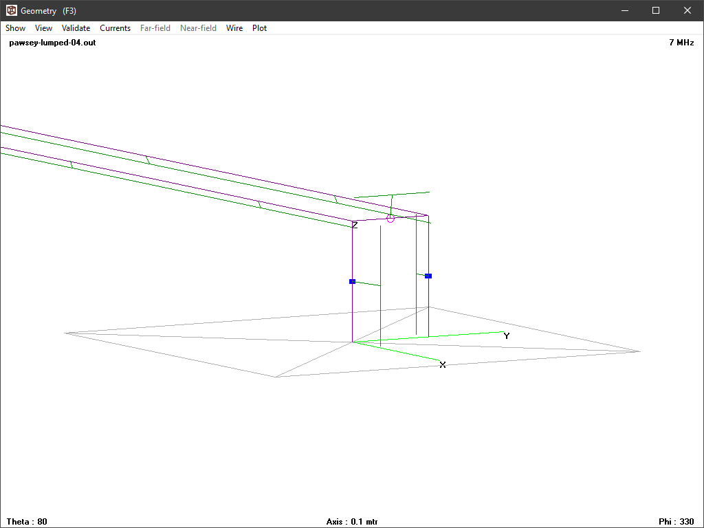
Guanella’s 1:1 balun and his explanation gave Guanella’s equivalent circuit and analysis of an example air cored choke of the type shown by Guanella.

The analysis was presented in an LTSPICE model of a ‘test bench’ implementation of the balun, and it showed that on a slightly asymmetric load, common balance was only good in a small region around the choke’s self resonant frequency of 41MHz.

One metric that is useful in indicating the effectiveness of a Guanella 1:1 balun in achieving current balance or reducing common mode current is the choking or common mode impedance Zcm of the stand alone balun.

Modern thinking and experience is that |Zcm| needs to be 1000Ω or higher for effective common mode reduction on many HF wire antennas, and considerably higher for some highly asymmetric antennas.

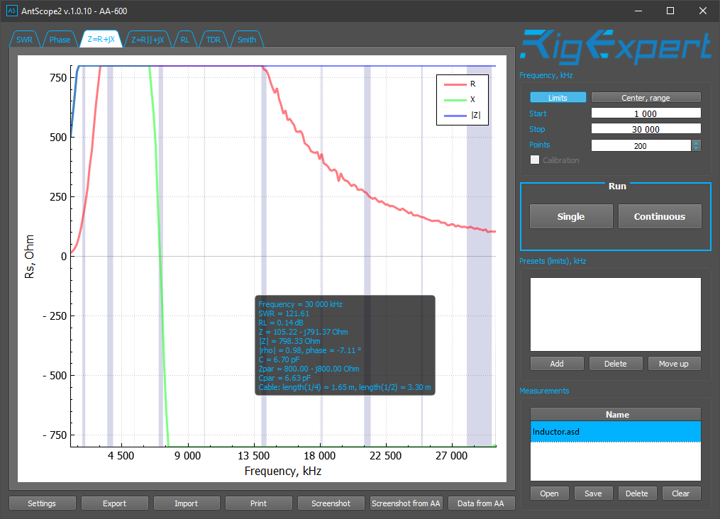
Zcm of the example air cored solenoid balun

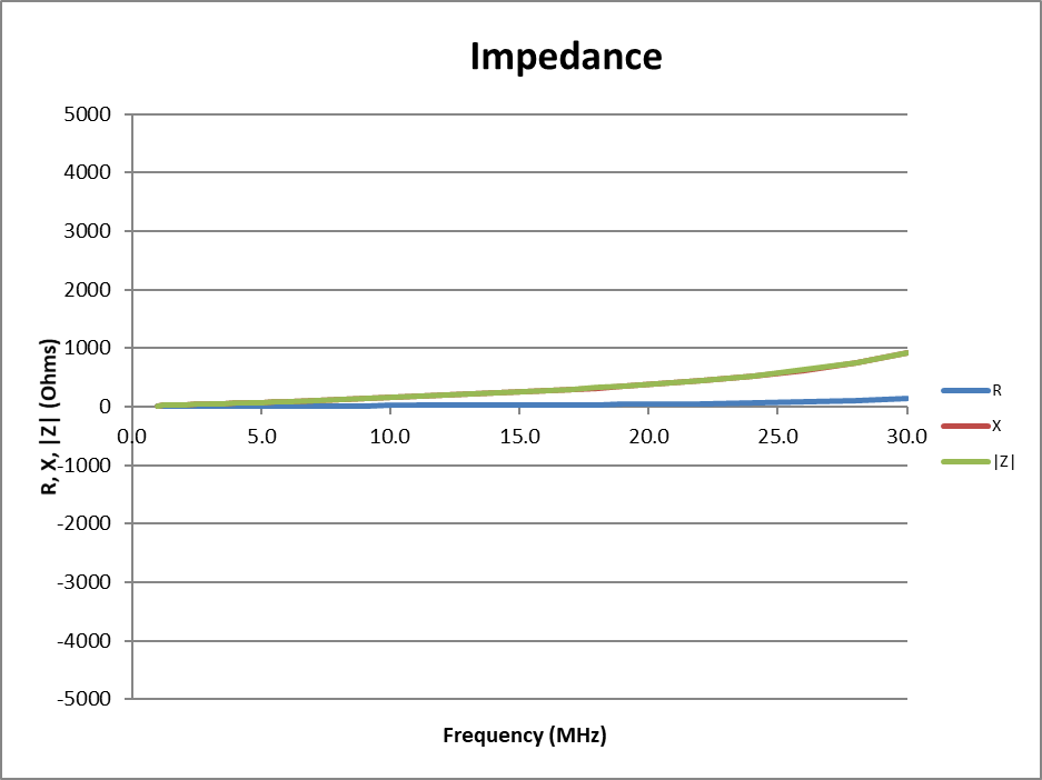
Above is Zcm for the example balun. It is very low at low frequencies and rises to 133+j914Ω at 30MHz. Continue reading Guanella’s 1:1 balun and his explanation – Zcm

Guanella’s 1:1 balun and his explanation

It is now 75 years since Guanella’s article “New methods of impedance matching in radio frequency circuits” described the form and operation of what we now commonly call a “Guanella 1:1” balun, but hams being hams also use other terms like “isolator”, “common mode choke”, “current choke” and some insist is it not a balun at all.

In fairness, Guanella did not call the thing a “balun”, but if we accept a very general meaning of balun to be any device intended to facilitate or permit a different state of balance to either side of itself, this is a balun.

Guanella’s description

Above is an extract from (Guanella 1944), and contains an almost complete description of the 1:1 balun. The ideal centre tapped transformers shows are a device for separating the differential and common mode currents so that appropriate elements can be used for those currents. Continue reading Guanella’s 1:1 balun and his explanation

Pawsey Balun – what is it good for?

The Pawsey Balun (or Pawsey Stub) is described as a device for connecting an unbalanced feed to a balanced antenna.

Above is a diagram of a Pawsey Balun used with a half wave dipole (ARRL).

Pawsey Balun on an asymmetric load reported model results in an asymetric dipole antenna, and showed very high common mode feed line current.

Pawsey Balun on an asymmetric load – bench load simulation showed that although the Pawsey balun is not of itself an effective voltage balun or current balun, it can be augmented to be one or the other.

So, you might ask what they do, what they are good for, and why they are used. Continue reading Pawsey Balun – what is it good for?

Pawsey Balun on an asymmetric load – bench load simulation

The Pawsey Balun (or Pawsey Stub) is described as a device for connecting an unbalanced feed to a balanced antenna.

Pawsey Balun on an asymmetric load reported model results in an asymetric dipole antenna, and showed very high common mode feed line current.

This article looks at two test bench configurations modelled in NEC.

The configurations are of a horizontal Pawsey balun for 7MHz constructed 0.1m over a perfect ground plane. The ‘balanced’ terminals are attached to the ground plan by two short 0.1m vertical conductors which are loaded with 33 and 66Ω resistances. At the other end, the horizontal transmission line is extended by two different lengths and connected to the ground plane using a 0.1m vertical conductor. The two extension lengths are almost zero and a quarter wavelength.

Zero extension

The total horizontal length from the ‘balanced terminals’ to the grounded end of the transmission line is a quarter wavelength for the Pawsey balun and a further 20mm making approximately a quarter wavelength in total.

Above is a plot of current magnitude and phase from 4NEC2. The current on the two vertical conductors containing the 33 and 66Ω loads is quite different, and the product gives load voltages that are approximately equal in magnitude and opposite in phase. Continue reading Pawsey Balun on an asymmetric load – bench load simulation

Pawsey Balun on an asymmetric load

The Pawsey Balun (or Pawsey Stub) is described as a device for connecting an unbalanced feed to a balanced antenna.

Above is a diagram of a Pawsey Balun used with a half wave dipole (ARRL).

Whilst these have been quite popular with VHF/UHF antennas, the question arises as to how they work, and whether they are effective in reducing common mode current IIcm) for a wide range of load scenarios. Continue reading Pawsey Balun on an asymmetric load

A balun puzzle – discussion

A balun puzzle asked several questions of this VK5AJL balun which was cited online.

  • Under what circumstances is the current into one terminal of the secondary significantly different to the current out of the other terminal of the secondary?
  • Is this in fact a better current balun than voltage balun under some conditions? What?
  • Is it a good voltage balun?

Continue reading A balun puzzle – discussion

Measuring balun common mode impedance – #3

A correspondent having read my series Measuring balun common mode impedance – #1 related difficulties with his Rigexpert AA-230Zoom.

The articles showed some techniques for measuring common mode impedance of a current balun.

The following examples are of a test choke wound on a BN43-202 binocular core, and the results are quite similar to what might be expected of a broadband HF current balun. The measurements were made with a Rigexpert AA-600.

Above, the measurement result using RigExpert’s newest software Antscope2. Continue reading Measuring balun common mode impedance – #3

Small common mode choke for analyser antenna measurements using 2843000202 (BN43-202)

The project is design, implementation and test of a small common mode choke for use with an analyser for antenna measurements.

The choke must have medium to high Zcm from 1 to 30MHz. It is intended to be used with analysers supporting SOL calibration, so effectively any impedance transformation within the fixture is compensated and the reference plane is the load side terminals of the device.

The candidate core is a low cost #43 binocular ferrite core that is fairly easy to obtain.

Above is a first pass check of the likely Zcm at 1.8MHz using a Fair-rite 2843000202 (BN43-202) binocular core. These chokes have relatively low self resonance frequency so a value for Cs is supplied that delivers self resonance at around 5MHz. Zcm at 1.8MHz needs 8-9t, 8.5t will be used (ie the twisted pair enters one end of the binocular and leaves the other end for convenient layout). (8.5t is not strictly correct, but it is a close approximation in this case.)
Continue reading Small common mode choke for analyser antenna measurements using 2843000202 (BN43-202)

Geometry factors for some common Fair-rite binocular ferrite cores

Designing with some common Fair-rite binocular ferrite cores can be frustrating because different parameters are published for different material types, and some are controlled for different parameters.

An approach is to derive the key geometry parameter from the published impedance curves and published material complex permeability curves.

For example, the above curves for a 2843002402 (also common known as a BN43-2402) were digitised and iteratively Calculate ferrite cored inductor (from Al) used for find the value of Al that gives the observed value for Z at 10MHz on the chart above. Continue reading Geometry factors for some common Fair-rite binocular ferrite cores