The OCF short vertical dipole for HF has become popular, particularly disguised as a flag pole for low impact installations and encouraged by claims of outstanding performance. The antenna was described in QST and a commercial version was available at time of writing.
The rationale for the design is that it is a short dipole, not requiring radials, and feed point offset downwards by 30% as an optimal value for performance (driven by often unsound assessments of coax loss).
Claims include:
Off-Center Fed Vertical Dipole design means no radials, 90% efficient or better across 80m – 10m
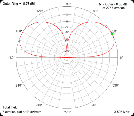
Above is the promising gain plot for one of the commercial implementations, it is only one S point (6dB) behind a quarter wave vertical with 4 buried radials.
The description as an OCF vertical dipole implies that the upper and lower ends of the nominal radiating element are current nodes / charge antinodes, and that a current antinode occurs somewhere midway between upper and lower ends.
Though there are descriptions by hams on how to make these things and how they work, and there are commercial implementations playing to the market and making what seem like pretty extravagant claims, there is a dearth of measurement or even credible models of the antenna system.
The article presents a model of such an antenna at 3.6MHz, a model that illustrates the potential for very low radiation efficiency from the antenna system.
Structure
The structure is a variation on Arnold Bailey’s (Bailey 1937) antenna system US Patent 2184729 (often known as a coaxial dipole or sleeve dipole though those terms commonly have other meanings in the ham world).
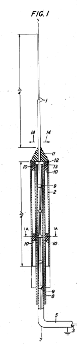
Above is a diagram of one implementation from Bailey’s patent. In Bailey’s antenna the coax (5) is routed upwards inside tube (8), insulated from and concentric to the lower tube (2); the shield connects to the top of the lower tube (2) and the inner conductor connects to the bottom of the upper conductor (1). (Tube (8) is only required for structural support, it could be insulating, and could be omitted.)
Bailey claims his invention deals with common mode current.
The parallel conducting surfaces comprising the inner surface of the tubular counterpoise and the outer surface of the coaxial outer conductor or sheath constitute a circuit having distributed constants of .such value as to prevent the establishment or production of undesired currents on the sheath outer surface…
Such distributed constants referring to the high impedance λ/4 resonance of the s/c stub formed by those elements.
He recognised the need for a common mode choke and it is this λ/4 common mode choke that is the essence of his invention 80 years ago.
OCF short vertical dipole for HF
The difference with the short OCF is that it is less than λ/2 overall, and the feed is offset below the centre (and tube 8 is omitted, a different support is used) all of which results in the s/c stub being just λ/70 in length.
NEC-4.2 model
NEC-4.2 is used for the model, and it permits the use of a driven ground electrode to assist in shedding common mode current to ground rather than following the feed line back the shack. Nevertheless further common mode choking of the feed line between transmitter and ATU may be warranted.
Key model parameters:
- 3.6MHz;
- 6m (λ/14) x 50mm diameter aluminium tube;
- broken at 1.2m from the bottom (“20% feed point”) and fed at that gap by an internal coax, shield connected to lower section and inner conductor to upper section;
- coax shield extends from the feed point inside the lower tube to ground level and is bonded to a 1.2m vertical electrode driven into the ground;
- 6 x Fairrite 2631101902 (#31) sleeves fitted to the lower end of the coax shield;
- an ATU attaches to the coax at the ground electrode connection;
- average ground (0.005/13).
This is a hypothetical model, it does not attempt to faithfully duplicate any particular design or product as none are described in sufficient detail to start building a specific model and then the model would need to be calibrated to a built antenna system including its environment and implementation detail.
Nevertheless, it contains important elements that are omitted from most explanations and models of this type of antenna.
The model is highly sensitive to the stated assumptions, so its conclusions might not be applicable to variations on the design… but it does highlight important elements of the context of this antenna SYSTEM.
The impedance of the s/c stub and the common mode choke appear in series between the bottom end of the tube and the ground electrode. Lets calculate their impedances.
Stub
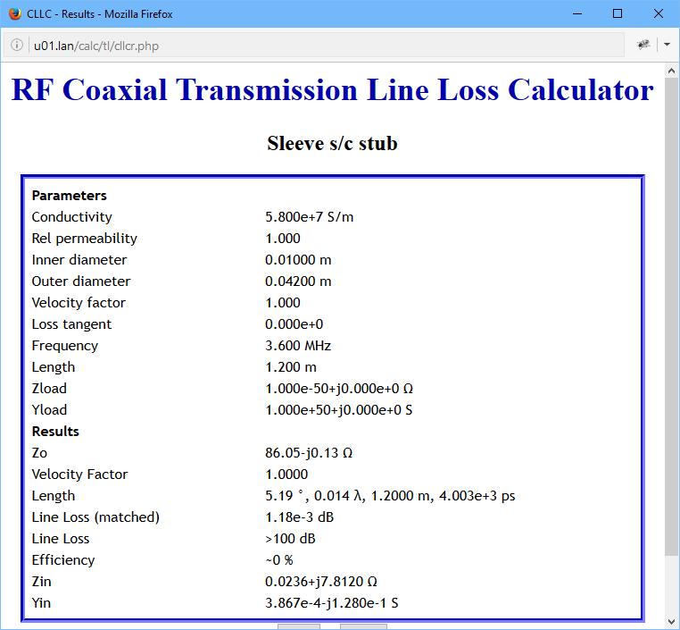
The coax shield inside the lower section of tube can be modelled as a 1.2m (λ/70) s/c transmission line stub. Lets assume that the coax is concentric to the tube, ignore the coax jacket, and the conductor diameters are 42mm and 10mm, we can calculate the input impedance of such a stub to be 0.02+j7.8Ω. In practice, it is likely to be lower due to poor concentricity.
The stub impedance is much lower than Bailey’s λ/4 stub, it will make negligible contribution to suppression of feed line common mode current.
Common mode choke
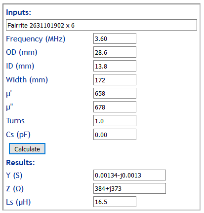
We can calculate the choking impedance of the 6 ferrite sleeves. Z=384+j373Ω. The sleeves chosen were Fairrite’s largest #31 sleeves that fitted over the cable and are a size or two larger than some designs.
The conductor between the bottom end of the tube and the ground electrode is loaded with the sum of the stub impedance and common mode choke impedance, Z=384+j381Ω. Note that the choke dominates this combined impedance.
Model results
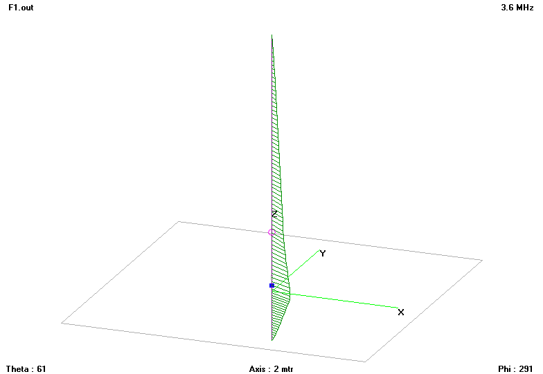
Above is the geometry of the model and plot of current magnitude and phase on the conductors. The current distribution is very important, it questions the explanation that this is a vertical dipole.

Above is the gain pattern of the antenna excluding feed line and ATU loss. Maximum gain is -21dBi, so efficiency will be low. In fact, radiation efficiency of the antenna excluding feed line and ATU loss is 0.272% or -25.65dB.
Dissipation in the common mode choke at 100W input to the feed point is 89.6W, a level it is unlikely to sustain for very long.
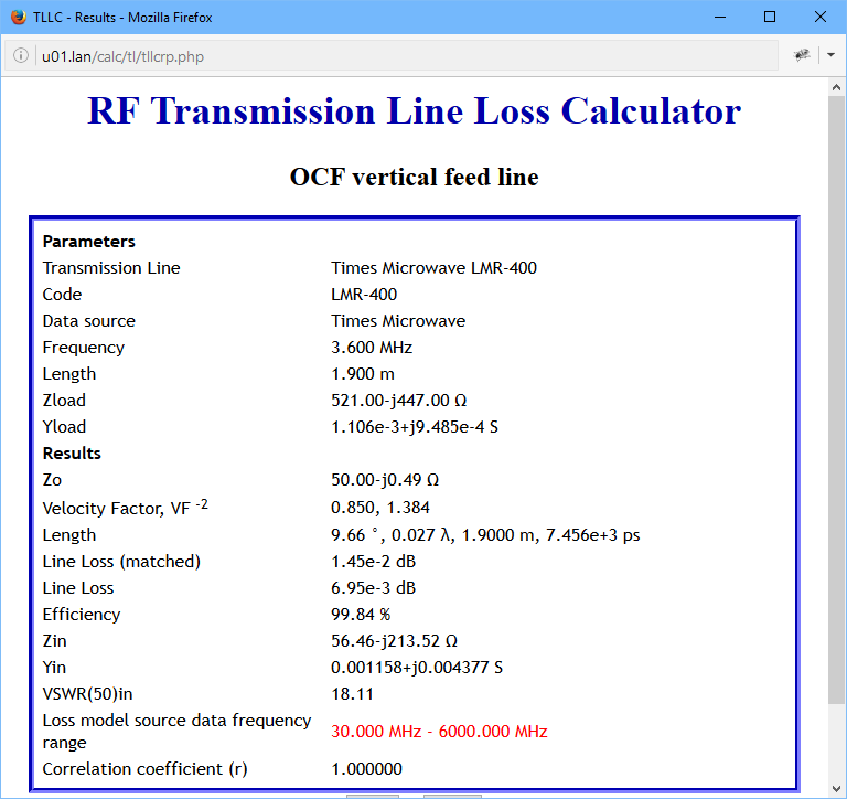
Impedance at the feed point is 521-j447Ω and the loss in 1.9m of LMR-400 from the ATU is calculated to be 0.007dB (less than the matched line loss because Z is so high, current is relatively low).
Fundamental design challenge
There is one stand out design challenge with this antenna, and it is fundamental to its operation.
The lower end of the tube is intended to be a point of large charge variation over an RF cycle, yet it is desirable that the coax connection to the ATU carries insignificant common mode current.
The question is whether there is some common mode choke construction that can reduce common mode current sufficiently to fulfil that objective and sustain modest power input to the antenna system.
Field strength measurement
The real test of this antenna system is to erect one in a clear site (ie away from buildings, vegetation, power lines etc, and measure the field strength from say λ/2 to 2λ. Though it pretends to be a dipole, a lossless implementation (incl perfect ground) will have a gain of 3 (4.77dB) and efficiency could be assessed in quite the same way as antennas for MW broadcast stations by making field strength measurements and factoring out the expected ground loss.
Conclusions
- An NEC model of a so-called OCF vertical dipole ‘flagpole’ antenna capturing the key elements of the construction does not support the proposition that it is a vertical dipole in nature, in fact the current distribution is very similar to that of a short grounded monopole.
- Claims of efficiency in excess of 90% beg the question what is meant by efficiency, it certainly is not Radiation Efficiency of the Antenna System.
- The model’s common mode choke is hopelessly ineffective, it is a common mode choke in name only, a sales gimmick perhaps.
- Measurement of common mode current on a built antenna should provide evidence of its effectiveness or otherwise.
- The NEC model of the antenna at 3.6MHz suggests gain is perhaps 15dB lower than claimed by some and some 25dB poorer than a lossless monopole antenna system.
- Field strength measurement of a built antenna factoring ground losses should lead to a meaningful confirmation or otherwise of design and product claims.
References
- Bailey, A. Apr 1937. Antenna system, US Patent US2184729.