The lightning ground conductor shown at Mast ground rework might at first seem excessive, this article sets out the rationale.
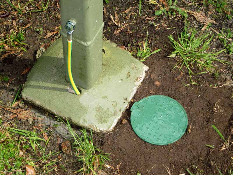
The connection to a 2.4m copper clad steel driven electrode (under the green cover) is 35mm^2 copper.
The nature of lightning protection sizing
Lightning protection sizing is a risk management regime driven by the mechanisms of lightning and variation in distribution.
It is not surprising then that regulatory standards in different distributions broadly use similar design methods but set different practices for implementation in the jurisdiction.
So, let’s go standards shopping… what we are looking for is guidance on the energy (or work) that is directed to heating the down conductor, and choosing a conductor size that will sustain not just a single stroke, or an average stroke, but most events that may include many strokes in a short period of time.
Calculation of temperature rise
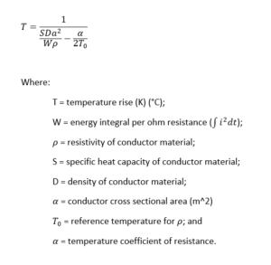
The following expression was derived to calculate the approximate temperature rise of the conductor due to lightning down current. The expression assumes no heat loss from the conductor during the event, and the DC resistance of the conductor is used.
 AS 1768

In Australia and New Zealand, AS 1768 pertains, and my now expired AS 1768-1991 gives guidance in Table A1 in a parameter entitled Specific Energy. It is described as the integral of i^2 dt in A^2s, but it is equivalent to the work W (J) per resistance R (Ω) of conductor resistance.
AS 1768-1991 gives the Specific Energy (W/R) for the whole flash for 99% of events as not more than 5e5 A^2s (or J/Ω).
We can then find a cable size that accommodates that energy with acceptable temperature rise (assuming that all of the energy is used to heat the conductor, none is lost externally during the very short event time).
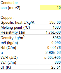
Above is an example calculation for 10mm^2 (#7) copper, the smallest standard size that will not sustain insulation damage from the temperature rise (25.5°).
IEC 62305
IEC 62305 pertains to Europe, and although I do not have a copy, it appears from citations that IEC 62305 sets a W/R parameter for 1e7J/Ω for Lightning Protection Level 1.
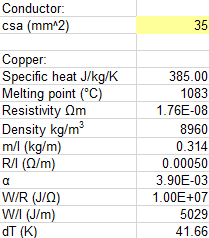
Above is an example calculation for 35mm^2 (#2) copper, the smallest standard size that will not sustain insulation damage from the temperature rise (41.7°).
NFPA 780 2004
For Class II structures (>23m height) minimum main conductor is 58mm^2, for Class 1 structures it is 29mm^2.
Conclusions
There are well established methods for design of lightning protection, and although the underlying methods are similar for AS 1768 and IEC 62305, the design thresholds are quite different.
The calculated minimum V75 copper cable to withstand 99% of events depends on the standard used:
- AS1768-1991: 10mm^2;
- IEC 62305: 35mm^2; and
- NFPA 780 2004: 58 or 29mm^2.
.