NEC requires the user to define a model structure as a set of geometry elements. It includes two powerful cards that make definition of the structure simpler and more reliable, they are the GM card for coordinate transformation and GX card for reflecting a structure in coordinate planes.
This tutorial demonstrates the use of these cards to define what might appear to be a fairly complex hypothetical NVIS antenna scenario quite simply, and more importantly, reliably. I say reliably because the logical definition of the model based on similar elements already defined, the more confident the developer can be that they are indeed similarly defined, the differences are explicit, and that they are properly connected.
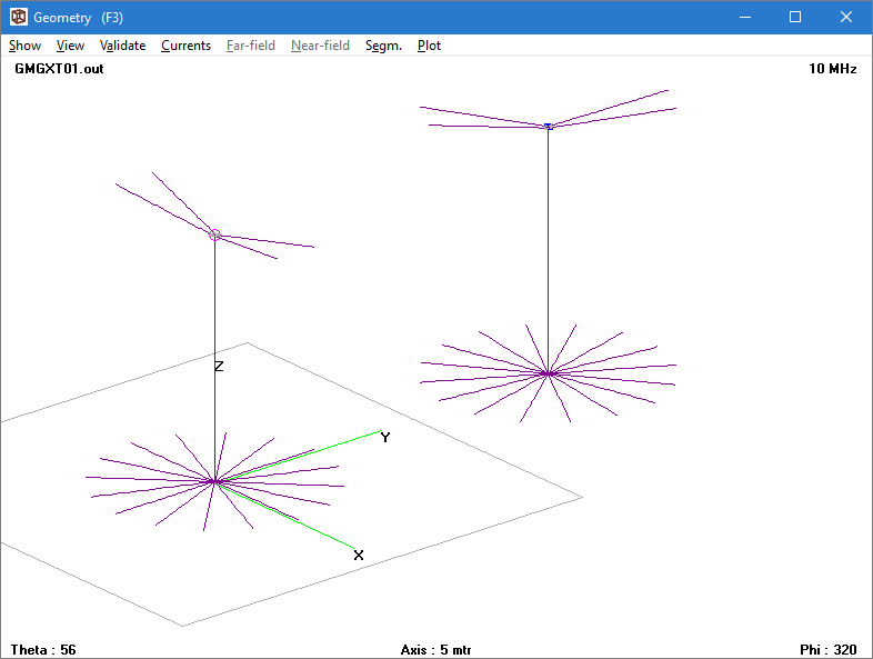 Above is a model to explore coupling from a tx antenna to a nearby rx antenna, The scenario contains 52 wire elements which one could naively define using 52 GW cards.
Instead, we will define it with far fewer GW cards and use model symmetry, rotation and translation to define the model.
The following is a 4NEC2 card deck which runs without errors using the NEC-4.2 engine. It contains inline comments that describe what the following card does. Note that the inline comment syntax and symbol usage (SY cards) is 4NEC2 specific and may not work in other packages. Further, whilst NEC allows inline comments in this style, unfortunately it consolidates them all at the start of the file upon saving.
CM GM, GX tutorial 4NEC2 deck
CE
SY f=10 'frequency
SY l1=3 'len of dipole leg
SY a1=10 'angle of dipole leg from Z plane
SY a2=15 'angle of dipole leg from Y plane
SY h1=10 'height of structure above ground
SY h2=0.1 'height of radials above ground
SY o1=0.05 'feed offset
SY r1=0.01 'dipole leg radius
SY d1=10 'distance to second antenna
SY l2=l1 'radial length
SY n=16 'number of radials
'define basic dipole leg length and radius
GW    1    50    0    0    0    l1    0    0    r1
'tilt up, out and offset it
GM    0    0    0    -a2    a1    o1    o1    0    1
'define connecting link
GW    2    1    o1    0    0    o1    o1    0    r1
'mirror the one leg structure
GX    2    010
'mirror the two leg structure
GX    4    100
'define the feed link
GW    10    1    -o1    0    0    o1    0    0    r1
'raise it all to height
GM    0    0    0    0    0    0    0    h1    1
'define mast
GW    20    50    0    0    h2    0    0    h1-o1    0.01
'define radial
GW    22    20    0    0    h2    l2    0    h2    r1
'replicate radials
GM    0    n-1    0    0    360/n    0    0    0    22
'replicate antenna
GM    100    1    0    0    60    0    d1    0    1
GE    -1
LD    0    110    1    1    50    0    1
GN    2    0    0    0    13    0.005
EK
EX    0    10    1    0    1    0    0
FR    0    0    0    0    f    0
EN
Note:
- That there are only 5 GW cards to define the structure of 52 conductors. We can be confident after a minimum of checking that the structure has the desired symmetry / balance, and the second antenna is indeed a faithful copy of the first.
- The first wire is defined simply along the X axis by its length and then rotated into the desired position, there is not need to define the 3D coordinates of the wire in its final position, let NEC do the calculations.
Some further exercises for the reader:
- What is the isolation(in dB) between transmitter on the left antenna and the 50Ω load inserted at the feed point of the second antenna?
- What if the load on the second antenna was matched, what is the isolation?
- What if the second antenna was parallel to the first?
- What is the difference in radiation efficiency if the 16 radials are reduced to 4?